Method for preventing band-break during continuous annealing process of band steel and its control system
A technology of annealing process and control system, applied in manufacturing tools, furnaces, heat treatment equipment, etc., can solve the problems of hysteresis, inability to prevent deviation in time, broken belt accidents, limited number of industrial TV monitoring devices, etc., to avoid belt breakage The effect of accident, installation and maintenance convenience
- Summary
- Abstract
- Description
- Claims
- Application Information
AI Technical Summary
Problems solved by technology
Method used
Image


Examples
no. 1 example
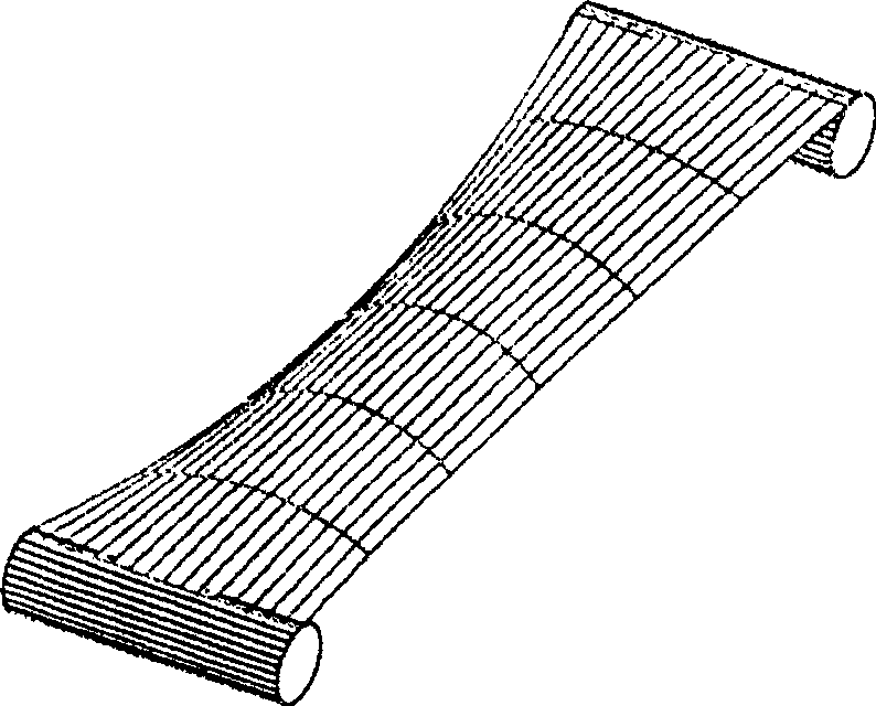
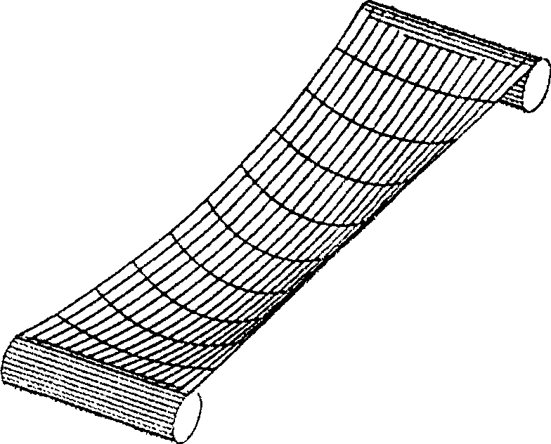
[0035] When the strip is suspended between the two supporting positions of the continuous annealing unit decoiler and the inlet looper (for example, the contact position of the conveyor roller and the strip), the tension is set to be small, so the strip basically assumes a shape under the action of gravity. Such as image 3 Shown in the shape of a suspension cable, the schematic diagram is a cross-sectional schematic diagram of the strip steel hanging between the two supporting positions of the continuous annealing unit decoiler and the inlet looper, which is taken along the strip conveying direction (hereinafter referred to as the longitudinal direction) Hereinafter, the cut surface is referred to as a longitudinal section. When the strip is divided into a plurality of long and narrow longitudinal regions along the longitudinal direction, the undulating shape of the strip surface makes the longitudinal regions of the strip suspended between the two conveyor rollers have different...
no. 2 example
[0068] The second embodiment of the method according to the present invention is described below.
[0069] In the first embodiment, only the strip shape data is used to set the passing speed and tension of the strip steel in the continuous annealing furnace. In this embodiment, the strip shape data is also used to set the strip correction angle.
[0070] When a unilateral wave occurs, due to the uneven distribution of tension on both sides of the strip, the strip deviation will inevitably occur. For this reason, a closed-loop feedback control composed of a deviation measurement device and a deviation correction mechanism is installed in the continuous annealing furnace. To be corrected. Such as Figure 6 As shown, the correction mechanism of the continuous annealing unit includes correction rollers 6a and 6b arranged in the traveling direction of the strip. By changing the angle between the correction rollers (that is, the correction angle of the strip), the traveling direction of...
no. 3 example
[0085]Figure 8 It shows a schematic diagram of a control system for implementing the method in the above-mentioned embodiment. The system includes a flatness detection unit 4 and a control unit 5.
[0086] Such as Figure 8 As shown, the flatness detection unit 4 is installed between the continuous annealing unit decoiler 1 and the entrance looper 2 to measure the strip shape data between the continuous annealing unit uncoiler and the entrance looper 2. The control unit 5 includes a board passing speed and tension setting module 5a and a correction roller included angle setting module 5b connected to the flatness detection unit 4 and a continuous annealing unit (not shown), wherein the module 5a is based on the flatness detection unit 4 The measured flatness data sets the speed and tension of the strip steel and instructs the continuous annealing unit to run at the set speed and tension. The module 5b sets the deviation correction based on the flatness data measured by the flatne...
PUM
 Abstract
Description
Claims
Application Information
 - R&D
- Intellectual Property
- Life Sciences
- Materials
- Tech Scout
- Unparalleled Data Quality
- Higher Quality Content
- 60% Fewer Hallucinations
Browse by: Latest US Patents, China's latest patents, Technical Efficacy Thesaurus, Application Domain, Technology Topic, Popular Technical Reports.
© 2025 PatSnap. All rights reserved.Legal|Privacy policy|Modern Slavery Act Transparency Statement|Sitemap|About US| Contact US: help@patsnap.com