Method and apparatus for concrete damage detection based on impedance imaging

A technology for damage detection and detection equipment, which is applied in the direction of material resistance and can solve the problems of large detection workload, inability to realize real-time monitoring, and limited detection depth.

Inactive Publication Date: 2009-04-08
SICHUAN UNIV
View PDF6 Cites 0 Cited by
  • Summary
  • Abstract
  • Description
  • Claims
  • Application Information

AI Technical Summary

Problems solved by technology

In view of its detection principle, there are the following problems: (1) An antenna must be used to approach the detection object during this detection operation, so the detected area is small. If the entire concrete structure is to be fully detected, each area must be scanned in turn, resulting in a large amount of detection work. (2) When used for internal defect detection, it is required that the dielectric constants of two adjacent substances differ greatly in order to obtain enough reflected energy to form a radar image. For environments with high conductivity, such as humid environments, the resolution is very high Low; (3) The detection depth is limited, so real-time monitoring cannot be realized, and the development of fractures cannot be predicted
[0006] For optical fiber sensing and detection, the optical fiber must be embedded in advance, so it can only detect cracks at the position where the optical fiber is embedded
In addition, in actual engineering applications, the severe environmental conditions of concrete construction pose a great threat to the survival of precise and thin sensing optical fibers

Method used


Image

  • Method and apparatus for concrete damage detection based on impedance imaging
  • Method and apparatus for concrete damage detection based on impedance imaging
  • Method and apparatus for concrete damage detection based on impedance imaging

Examples


Embodiment 1

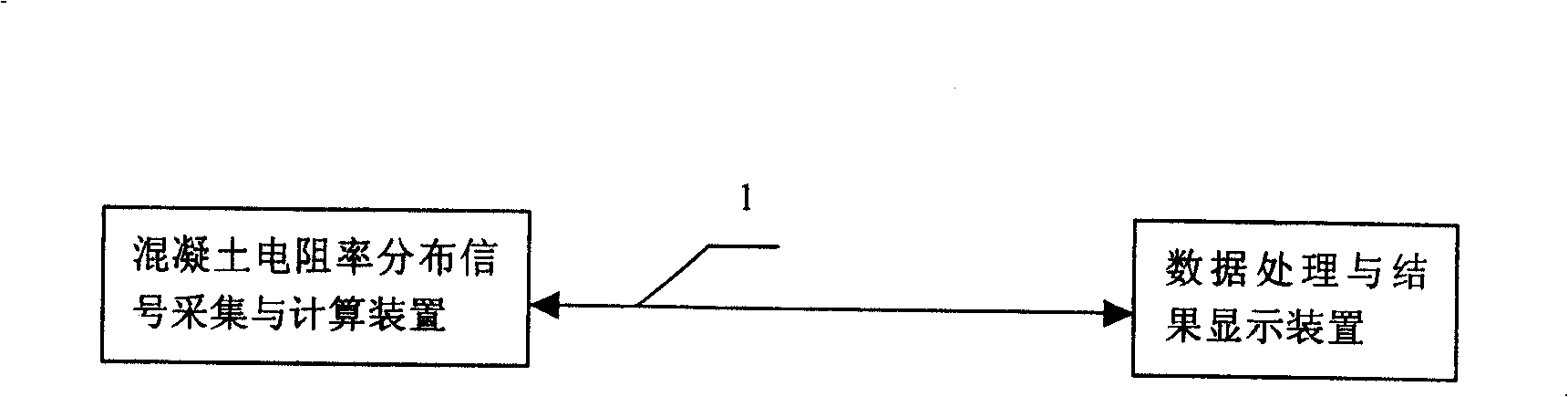
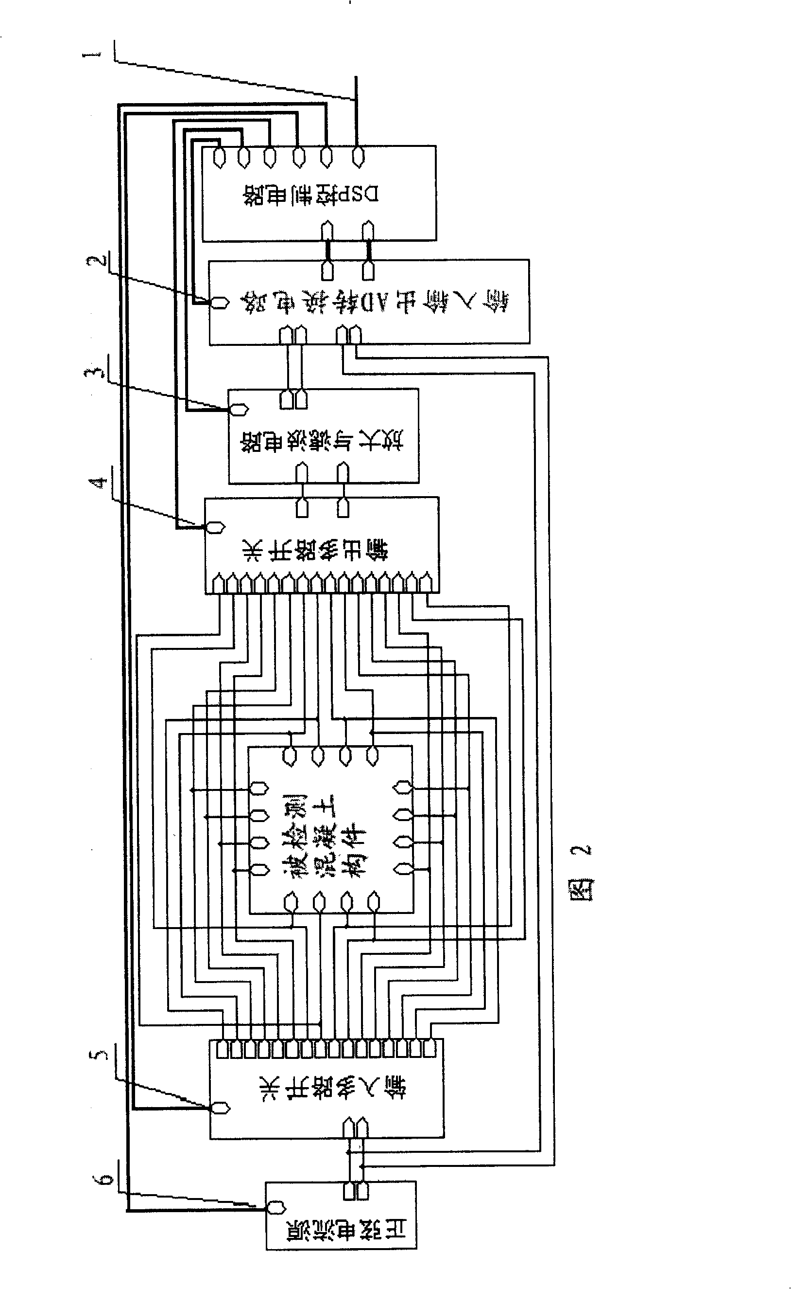
[0085] The structure of the detection equipment described in this embodiment is as follows: figure 1 As shown, it includes a concrete resistivity distribution signal acquisition and calculation device, a data processing and result display device, and the two devices are connected through a communication bus 1 . The data processing and result display device adopts industrial control computer; the structure of the concrete resistivity distribution signal acquisition and calculation device is shown in Figure 2, including sinusoidal current source, input multi-way switch, output multi-way switch, amplification and filter circuit, AD conversion circuit, DSP control circuit.

[0086]As shown in Figure 2, the concrete component to be tested is a square component, and four copper electrodes are evenly distributed on each side of the component, a total of sixteen electrodes. The output end of the sinusoidal current source is connected with the input multi-way switch and the AD convers...

Embodiment 2

[0095] In this embodiment, the damage of a square concrete member is detected, and the concrete member is set as Figure 14 Shown crack, with the detection equipment described in embodiment 1, step is as follows:

[0096] (1) Set 16 red copper electrodes on the concrete component to be tested, and 4 electrodes are evenly distributed on each side of the concrete component, as shown in Figure 2.

[0097] (2) Connect the excitation input port of each electrode provided on the concrete component to be detected with the input multiplex switch of the detection equipment, and connect the response output port of each electrode provided on the concrete component to be detected with the output multiplex switch of the detection equipment , the connection method is shown in Figure 2.

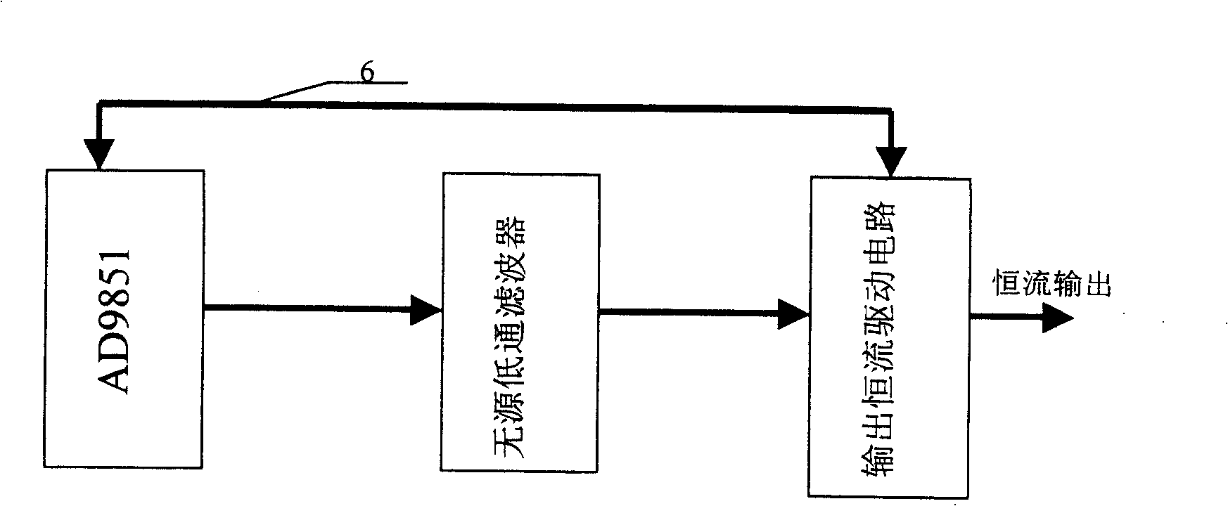
[0098] (3) To operate the detection equipment, the industrial control computer sends control commands to the concrete resistivity distribution signal acquisition and calculation device, and the sinusoidal ...


PUM


Abstract

This invention relates to a method and apparatus for concrete damage detection based on impedance imaging, which comprises the following steps: (1) setting multiple electrodes on target; (2) connecting the excitation input ports of former electrodes to the multi-way input switch; (3) forcing the drive sine current to every two electrodes by turns, measuring the current amplitudes and phases; (4) computing resistance distribution in the concrete; (5) acquiring and storing computation data to compare with given data for analysis.

Description

technical field [0001] The invention belongs to the field of damage detection of concrete components, in particular to a method and equipment capable of real-time monitoring of the internal conditions of concrete components. Background technique [0002] Health diagnosis and damage detection of concrete components have an important impact on the development of the national economy and people's lives. The technology of health diagnosis and damage detection of concrete components is one of the main problems that need to be overcome in the world today. [0003] At present, the methods used to detect internal defects in concrete mainly include ultrasonic testing, radar testing and optical fiber sensing testing, among which ultrasonic testing is the most widely used. [0004] The basic principle of ultrasonic testing is to compare the relative changes of parameters such as sound velocity, amplitude and frequency when the ultrasonic pulse passes through the defect or damage, and c...

Claims


Application Information

Patent Timeline
Patent Type & Authority Patents(China)
IPC IPC(8): G01N27/20
Inventor 李碧雄莫思特
Owner SICHUAN UNIV
Why Eureka
Try Eureka