
Memory bus wiring structure and wiring method for low profile display card

A wiring structure, display card technology, applied in the direction of instruments, electrical digital data processing, printed circuit components, etc., can solve the problems of unable to increase the memory capacity of the display card, memory bus bandwidth, noise interference, time difference, etc., to achieve improved memory Effect of capacity and memory bus bandwidth

Inactive Publication Date: 2009-04-15
TUL CORP
View PDF3 Cites 1 Cited by
  • Summary
  • Abstract
  • Description
  • Claims
  • Application Information

AI Technical Summary

Problems solved by technology

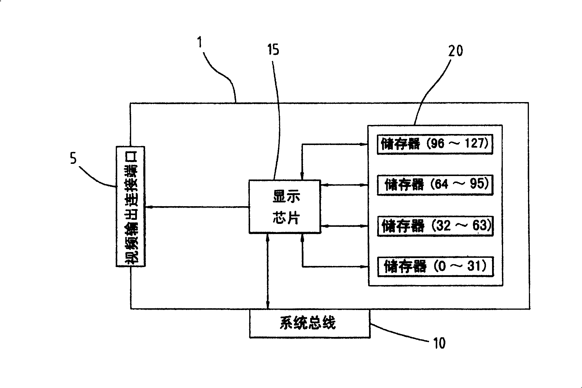
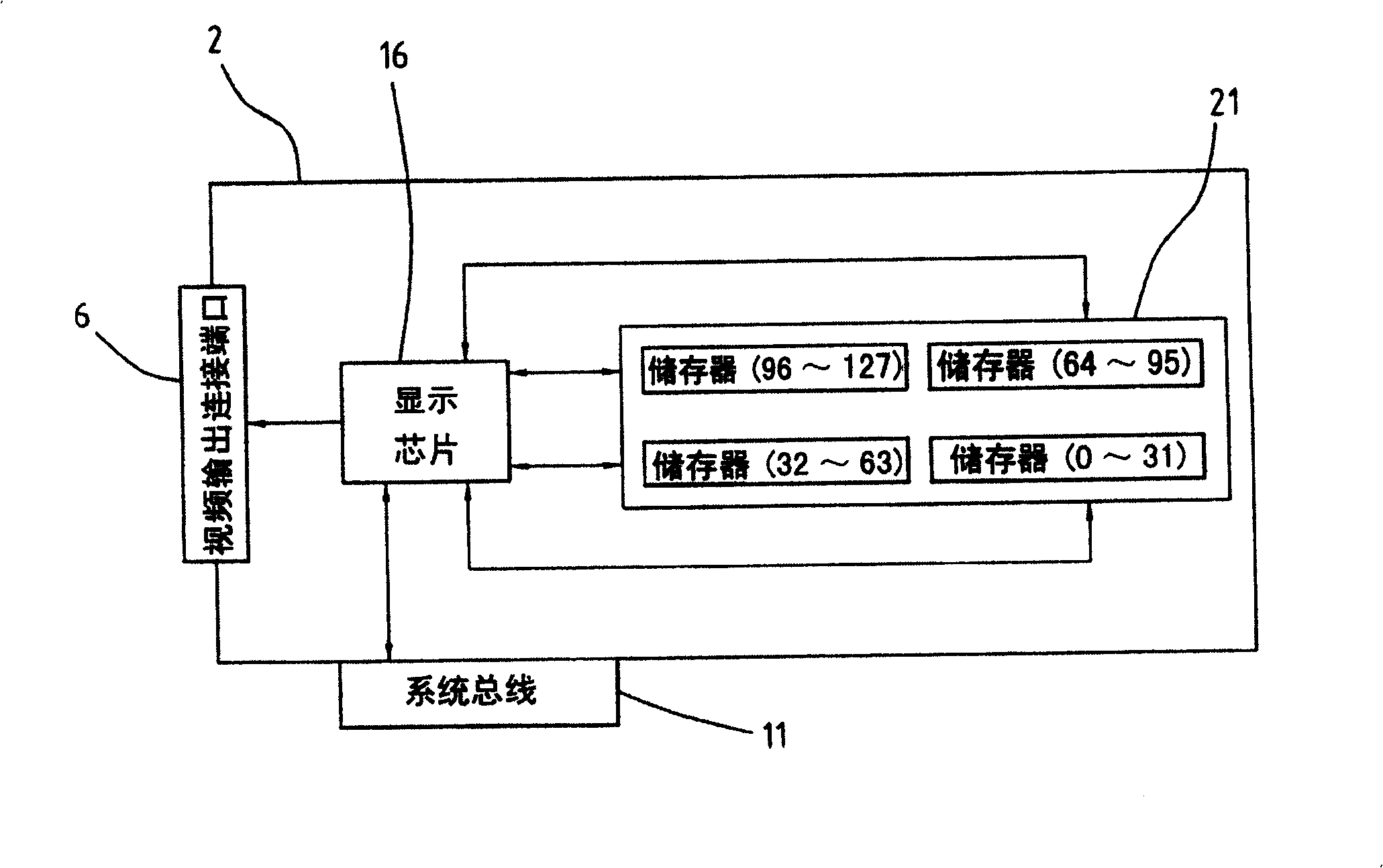
because figure 1 and figure 2 Due to the limitation of the installation position of memory components and the narrow board circuit substrate, the prior art implements wiring with the shortest distance, which will make the wiring method of the bus signal line a non-equidistant wiring method, which not only easily causes noise interference, but also in UHF Under the operation of the bus, there may be a time difference between the bus signal lines due to unequal line lengths. Therefore, the above two conventional wiring techniques are limited by the narrow board circuit substrate structure, and cannot increase the memory capacity and storage capacity of the display card. Bus bandwidth makes data processing slower

Method used

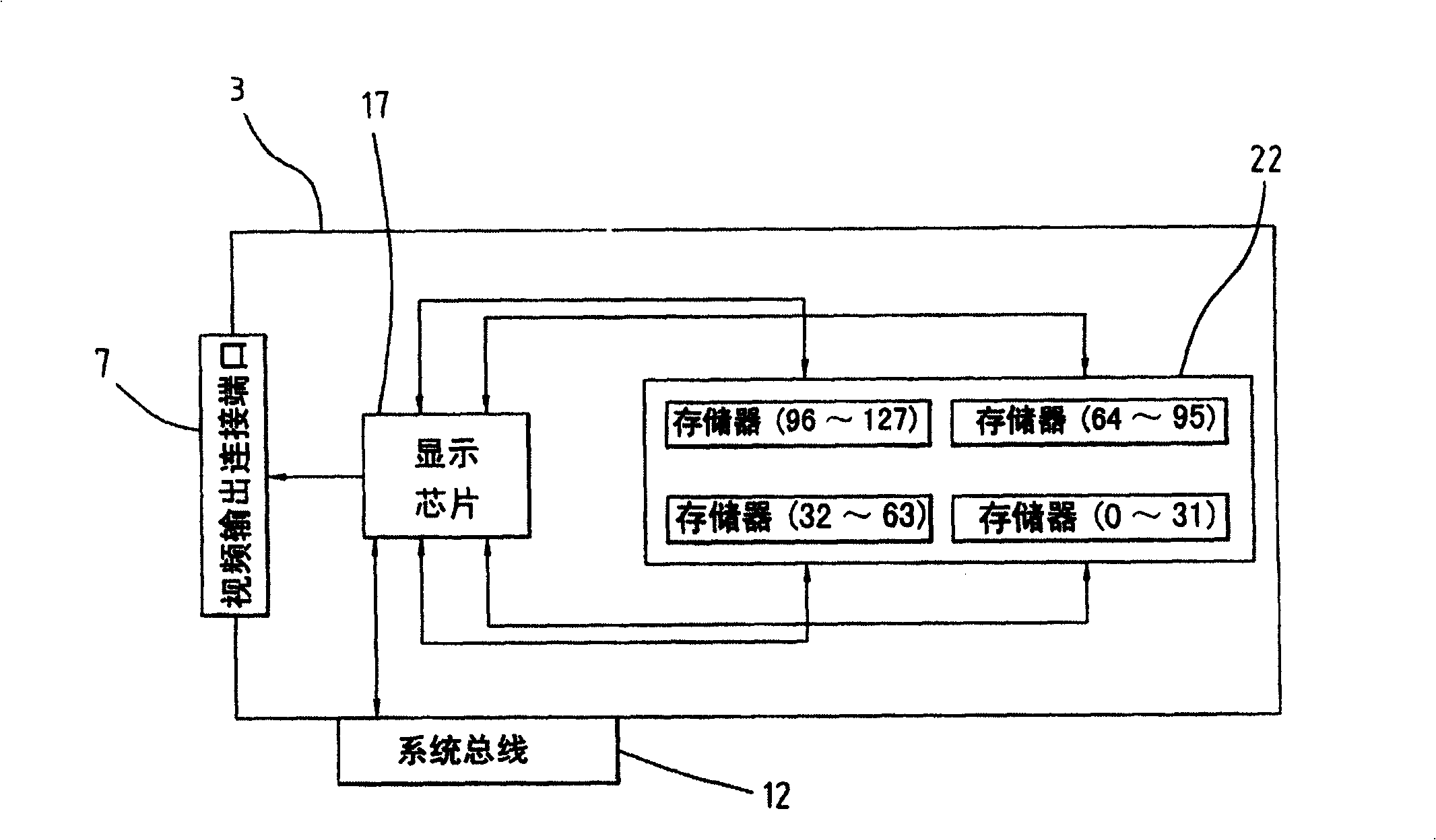

Image

  • Memory bus wiring structure and wiring method for low profile display card
  • Memory bus wiring structure and wiring method for low profile display card
  • Memory bus wiring structure and wiring method for low profile display card

Examples


Embodiment Construction

[0031] The present invention is a memory bus wiring structure and wiring method of a narrow-board display card. To achieve the above-mentioned purpose, FIG. 3 is a schematic diagram of the arrangement position of the electronic components of the present invention. The present invention provides a multilayer board structure with equidistant wiring, wherein the main components include: a substrate body 3, a display chip 17, multiple memories 22 on the front, multiple memories 24 on the back, video output connection ports 7 and a system bus 12 and other components.

[0032] According to a preferred embodiment of the present invention, such as Figure 3A As shown in ~B, the front and back of the substrate main body 3 are component installation areas, wherein the display chip 17 is arranged on the left side of the substrate main body 3, and the multiple memories 22 on the front and the multiple memories 24 on the back are arranged in a distributed manner. Corresponding positions o...


PUM


Abstract

The provided RAM-bus routing structure for narrow-board show card comprises: a base plate with multi-layer structure, a display chip, multiple memories, and signal wire. This invention can improve the defect of lacking bus frequency width in prior art.

Description

technical field [0001] The invention relates to a memory bus wiring structure and wiring method, in particular to an equidistant wiring structure and wiring method implemented in a narrow board display card. Background technique [0002] With the advancement of the electronic industry, people have more and more demands on computers, often in order to meet the characteristics of lightness, convenience, space-saving and efficiency, etc., so the computer structure is getting smaller and smaller, and, as electronic devices become more and more Therefore, for the design of the circuit substrate, especially for the wiring method of the signal lines, it is one of the main issues. If the user is using a mini computer or other computers with a small internal space in the casing, it is often impossible to use some computer software due to the insufficient memory capacity and memory bandwidth of the existing narrow board graphics card. [0003] According to the current wiring technolo...

Claims


Application Information

Patent Timeline
Patent Type & Authority Patents(China)
IPC IPC(8): G06F1/00G06F13/40H05K1/02
Inventor 王良吉赖恩赐彭成国
Owner TUL CORP
Learn More