Inverter device
A technology for inverters and switching devices, which is applied in relays, transportation and packaging, and the conversion of irreversible DC power input to AC power output. It can solve the problems of device size expansion, reduce the installation space, and ensure the insulation distance. Effect
- Summary
- Abstract
- Description
- Claims
- Application Information
AI Technical Summary
Problems solved by technology
Method used
Image
Examples
Embodiment 1
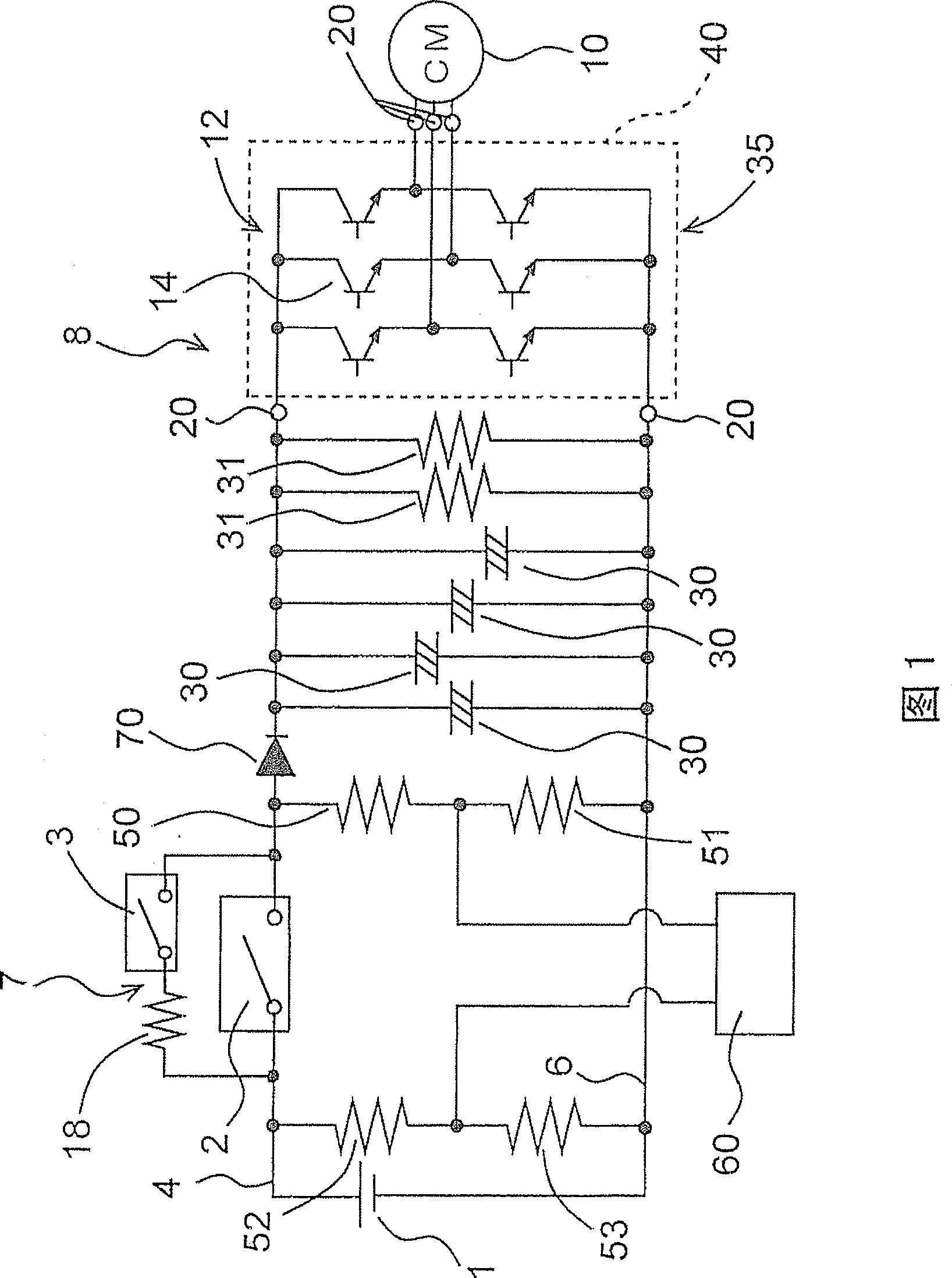
[0031] FIG. 1 is a power circuit diagram of an embodiment of an air conditioner for an electric vehicle provided with the inverter device 8 of the present invention.
[0032] In FIG. 1, 1 is the main battery which is a DC power supply of an electric vehicle, and supplies electric power to the electric compressor 10 of an air conditioner through the inverter apparatus 8 of this invention. Although the DC voltage is output from the battery 1, it is supplied to the electric compressor 10 (the motor of the electric motor): converted into pseudo-inverter by the inverter module 35 (the inverter of the present invention) of the inverter device 8 to be described later. Three-phase AC voltage.
[0033] The above-described inverter device 8 includes a switch 2 as a switching device or a charging circuit 7 as a charging device, four capacitors 30 . . , discharge resistors 31 and 31 , and an inverter module 35 .
[0034] The above-described inverter module 35 is formed by arranging the s...
Embodiment 2
[0055] Next, in conjunction with Figure 4 and Figure 5 Yet another embodiment of the present invention is described.
[0056] 4 is a power supply circuit diagram showing the air conditioner for an electric vehicle of the invention in this case, Figure 5 It is a perspective view which shows the inverter module 135 of this Example.
[0057] In FIG. 4, reference numeral 101 denotes a main battery as a DC power supply for an electric vehicle, and an inverter configured via a switch 102 or a charging circuit 107 as a charging device, a capacitor 130, a discharging resistor 131, and an inverter module 135 of the present invention, etc. The inverter device 108 supplies DC power to the electric compressor 110 of the air conditioner. Although the DC voltage is output from the battery 101, the electric compressor 110 is supplied with a voltage converted into a pseudo-three-phase AC by an inverter module 135, which will be described later.
[0058] The inverter module 135 is formed ...
Embodiment 3
[0077] Next, another embodiment of the above inverter module will be described with reference to FIG. 6 . FIG. 6 shows a power supply circuit diagram of an example of an air conditioner for an electric vehicle including the inverter module 235 in this case. In addition, in FIG. 6, and FIG. 4 and Figure 5 Components with the same symbols are components that perform the same or similar functions.
[0078] In FIG. 6 , 235 is an inverter module of the present embodiment, and the voltage converted into three-phase pseudo-AC by the inverter module 235 is supplied to the electric compressor 110 .
[0079] The inverter module 235 is formed by arranging the switching element group 112 for converting the voltage into a three-phase pseudo-AC voltage by switching inside the mold assembly 140, as in the above-described embodiment. The switching element group 112 includes a switching element 114 and a diode (not shown) for absorbing operation overvoltage, and is connected between the pos...
PUM
 Abstract
Description
Claims
Application Information
 - R&D
- Intellectual Property
- Life Sciences
- Materials
- Tech Scout
- Unparalleled Data Quality
- Higher Quality Content
- 60% Fewer Hallucinations
Browse by: Latest US Patents, China's latest patents, Technical Efficacy Thesaurus, Application Domain, Technology Topic, Popular Technical Reports.
© 2025 PatSnap. All rights reserved.Legal|Privacy policy|Modern Slavery Act Transparency Statement|Sitemap|About US| Contact US: help@patsnap.com


