Loopback protector for light monitor channel

A channel and loopback technology, applied in the field of synchronous protection of the entire network, can solve problems such as unstable loopback protection of optical monitoring channels

Inactive Publication Date: 2009-05-06
ZTE CORP
View PDF3 Cites 0 Cited by
  • Summary
  • Abstract
  • Description
  • Claims
  • Application Information

AI Technical Summary

Problems solved by technology

[0005] The purpose of the present invention is to solve the unstable shortcomings of the optical monitoring channel loopback protection in the existing system, provide a stable and reliable optical monitoring channel loopback protection device, and better meet the overall requirements of the Ministry of Posts and Telecommunications for the optical wavelength division multiplexing system. Technical regulations on optical monitoring channel

Method used


Image

  • Loopback protector for light monitor channel
  • Loopback protector for light monitor channel
  • Loopback protector for light monitor channel

Examples


Embodiment Construction

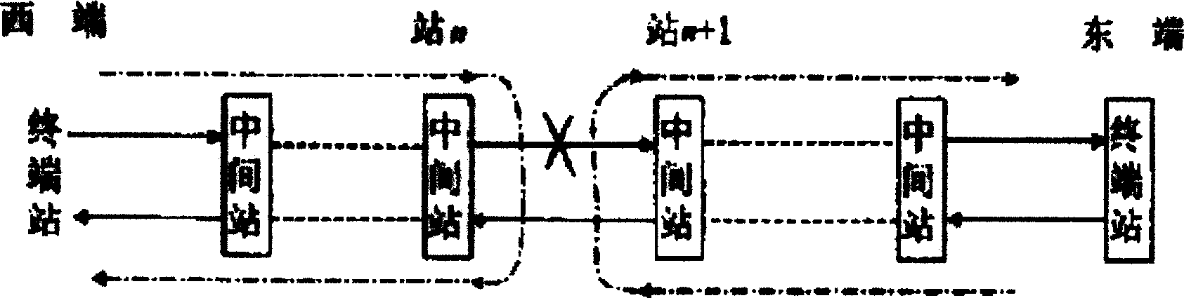
[0011] figure 1 It is a schematic diagram of the loopback protection function of the optical monitoring channel. When the fiber section between two repeaters is broken, such as the fiber section between the relay station n and the relay station n+1 is broken, the relay station n+1 will be activated. The clock is transmitted in the direction of the east terminal. That is, when a repeater fails, the repeater located downstream of the failure point will automatically start the backup clock on the repeater to loop the signal back to the terminal station, similar to the above-mentioned fiber break, and automatically cancel the loopback function when the fiber is restored. .

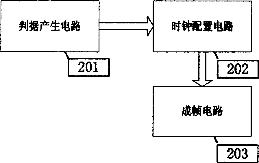
[0012] Combine figure 2 , Figure 4 Further explain the optical monitoring channel loopback protection device of the present invention, including a criterion generating circuit 201, a clock configuration circuit 202, and a framing circuit 203; firstly, data is collected in the criterion generating circuit, that ...


PUM


Abstract

The invention discloses the device of the loop back protection of the optical pilot channel. The device includes the criterion circuit, the timing clock allocation circuit and the framing circuit. The criterion generation circuit uses the LOS signal and the received optical power collected to determine whether the optical signal is lost or not. If the optical signal is lost, the timing clock allocation circuit reconfigures the timing clock of the system. The allocation circuit provides the timing clock needed by the framing circuit. The framing circuit turns the PCM data to the frame, impproves the reliability of the pilot channel and increases the quality of the ECC channel and public service channel.

Description

Technical field [0001] The invention relates to the protection of a synchronous clock loopback, in particular to the entire network synchronous protection of a monitoring channel in a dense wavelength division multiplexing optical transmission system. Background technique [0002] When the optical monitoring channel of the dense wavelength division multiplexing system adopts a network-wide synchronization method, one node in the network is used as the system master clock, and the other nodes extract the clock information of the upstream node from the optical path as the clock of the local node. This clock mode largely depends on the reliability of the network connection. Once the optical fiber is broken, the corresponding downstream node will lose the system master clock, causing the entire downstream link communication to be interrupted. [0003] In the dense wavelength division multiplexing optical transmission system, the optical monitoring channel is required to have a loopba...

Claims


Application Information

Patent Timeline
IPC IPC(8): H04J14/02H04B10/08H04B10/032
Inventor 石峰魏晓强
Owner ZTE CORP
Why Eureka
Try Eureka