Permanent magnet non-arching AC contactor

An AC contactor and permanent magnet technology, which is applied in the direction of non-polar relays, electromagnetic relays, electromagnetic relay details, etc., can solve the problems of inability to fundamentally eliminate arcs, high conduction loss, and high prices.

Inactive Publication Date: 2009-05-20
SHENYANG POLYTECHNIC UNIV
View PDF3 Cites 0 Cited by
  • Summary
  • Abstract
  • Description
  • Claims
  • Application Information

AI Technical Summary

Problems solved by technology

[0005] None of the above methods can fundamentally eliminate the arc, but only limit and help to extinguish the arc
Although the non-contact switches currently on the market are arc-free products, they are expensive, and because there are no mechanical contacts, the conduction loss is high, the overload capacity is poor, and the volume is large.

Method used


Image

  • Permanent magnet non-arching AC contactor
  • Permanent magnet non-arching AC contactor
  • Permanent magnet non-arching AC contactor

Examples


Embodiment Construction

[0020] The present invention will be further described below in conjunction with the accompanying drawings.

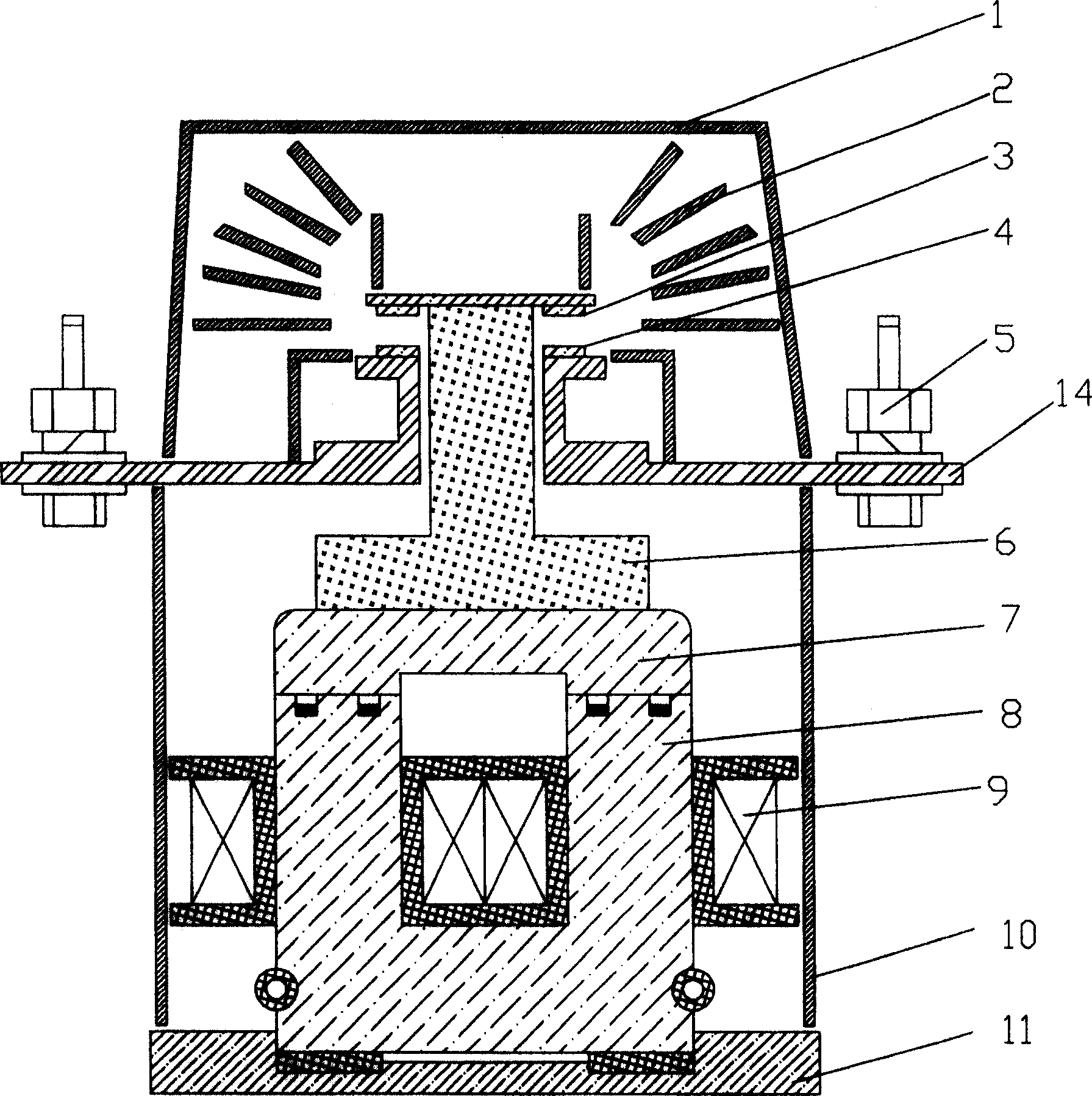
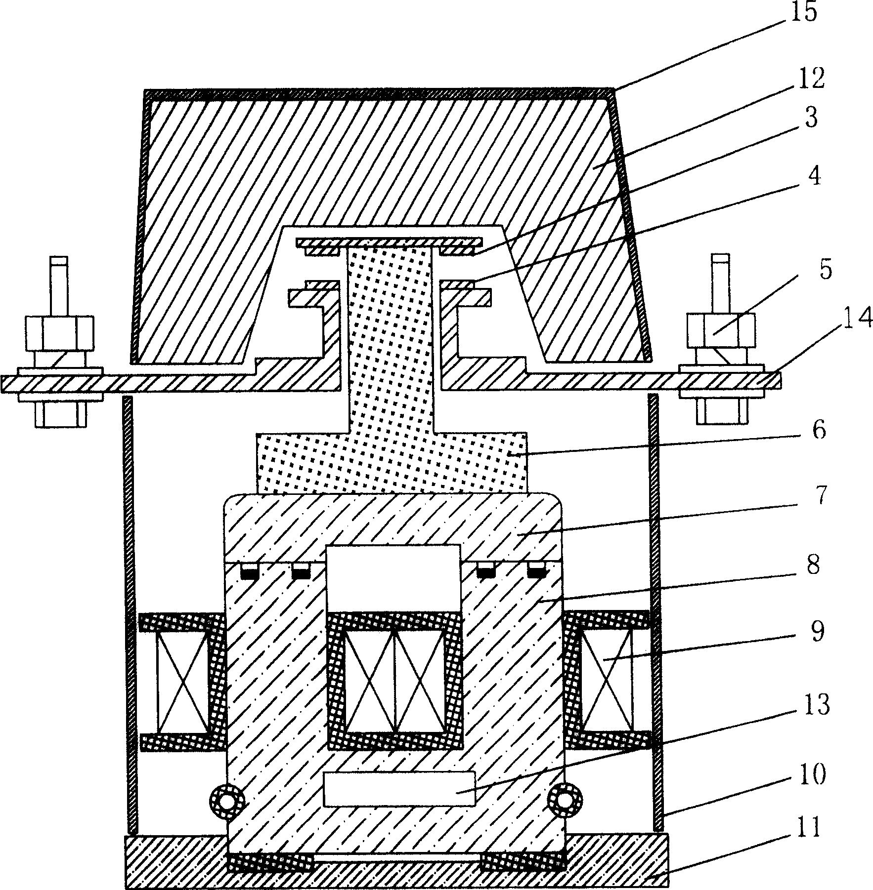
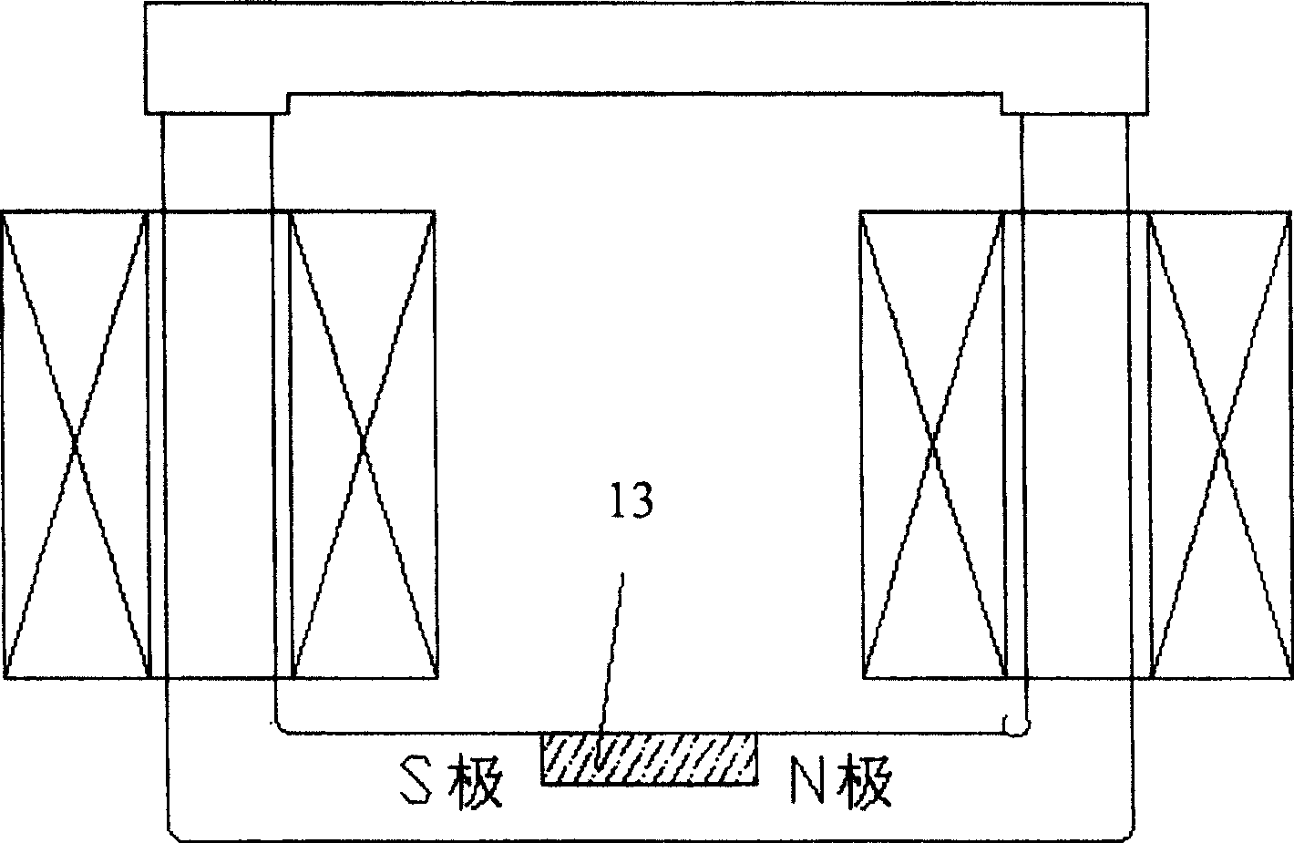
[0021] figure 2 Shown is a schematic cross-sectional view of the structure of this embodiment, which includes an upper end cover, a thyristor and a control part, a moving contact, a static contact, a main contact terminal, a movable support, a conductive rod, an armature, an iron core, a coil, and a permanent magnet. , shell and base, in which the thyristor and the control module replace the arc extinguishing part of the existing contactor, and a permanent magnet is added at the bottom of the iron core. The casing 10 is covered on the base 11 to form a cavity. In the cavity, the iron core 8 is fixed on the center of the base 11. The iron core 8 is concave, and the bottom of the iron core has a square groove for placing the permanent magnet 13. Coils 9 surround the two uprights, the tops of the two uprights form a closed magnetic path with the armature 7, the armature...


PUM


Abstract

This invention relates to a permanent magnet arcless AC contactor including a top cover, a thyristor and its control part, a magnet, a moving contactor, a static contactor, a primary contactor terminal, a moving bracket, a conduction rod, a gag bit, a core, a coil, a shell and a base, in which, the control part in the thyristor and the control part is composed of a control unit, a switch unit, an energy storage element and IGBT element, the control unit is connected with the thyristor, the switch element, energy storage element and the IGBT element, one end of which is connected with any phase in a three-phase voltage by a coil, the other end is connected to the other end of the voltage, both ends of the switch element and the energy storage element are connected with the coil, both ends of each contact point of the contactor are parallel to a pair of counter-parallel single-way thyristors then to be connected to the supply and the load.

Description

technical field [0001] The invention belongs to the field of low-voltage electrical appliances, in particular to a permanent magnet arcless AC contactor. Background technique [0002] When the traditional AC contactor is working, an arc will be generated during the pull-in and break-off process, and the coil must be energized to keep the contactor in the pull-in state after the contactor is closed. When the circuit is turned on and off, there are shortcomings such as strong arcs on the main contacts, which not only causes a lot of waste of electric energy, pollutes the surrounding environment, but also greatly reduces the electrical life of the contactor. [0003] Over the years, electrical workers have carried out a lot of work to improve various performances of contactors, such as energy saving, some use AC pull-in, DC hold; some use high-voltage DC pull-in, low-voltage DC hold, etc., although they have energy-saving functions , but the coil is still energized, it’s just ...

Claims


Application Information

Patent Timeline
Patent Type & Authority Patents(China)
IPC IPC(8): H01H51/01H01H50/64H01H47/02
Inventor 王俭蔡志远马少华厉伟
Owner SHENYANG POLYTECHNIC UNIV
Why Eureka
Try Eureka