Stator of slewing electric machine
A rotary motor and stator technology, applied in electrical components, electromechanical devices, electric components, etc., can solve the problems of increasing electromagnetic noise, inability to increase the overall rigidity of the coil end, and small elastic modulus, reducing electromagnetic noise and improving Rigidity and the effect of preventing exposure of the joint
- Summary
- Abstract
- Description
- Claims
- Application Information
AI Technical Summary
Problems solved by technology
Method used
Image
Examples
Embodiment 1
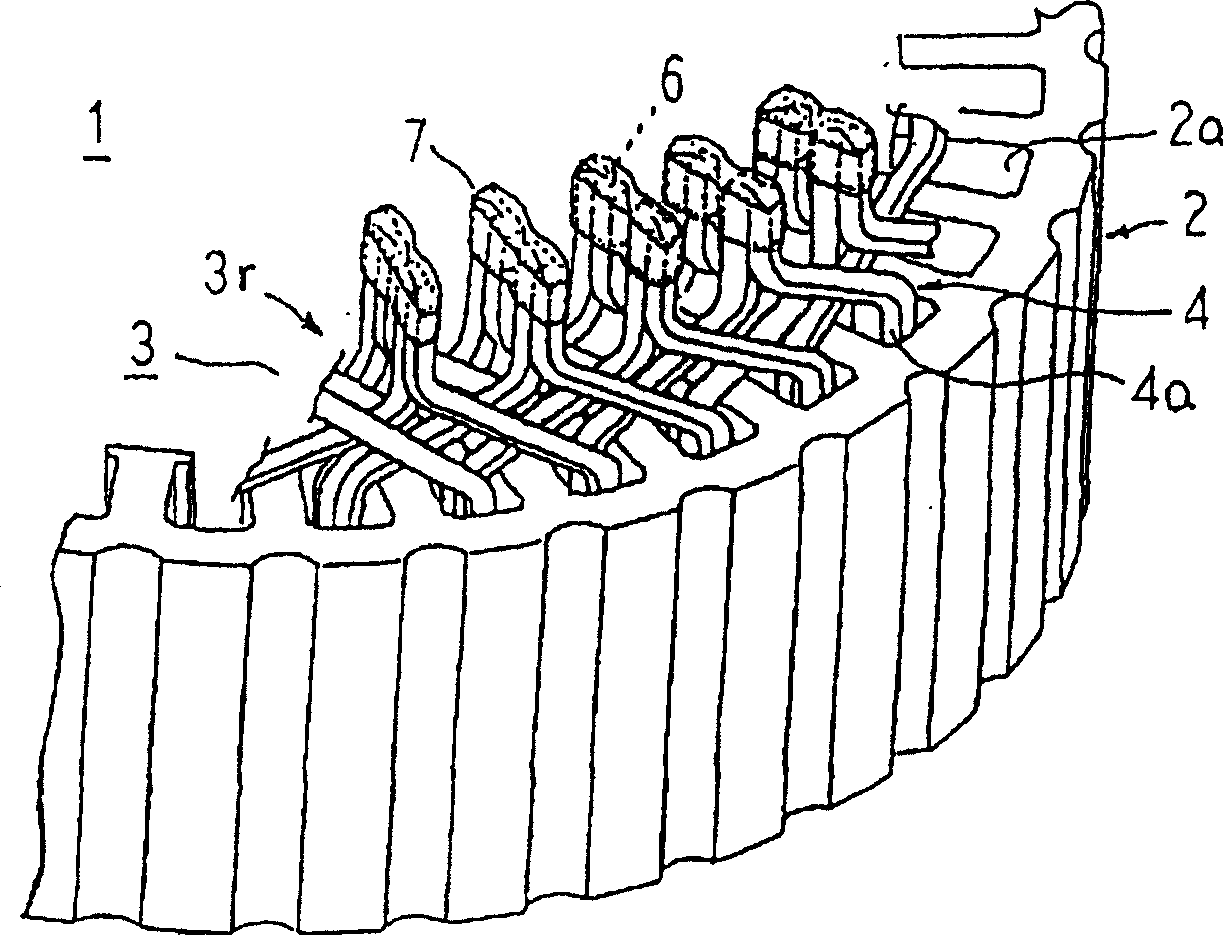
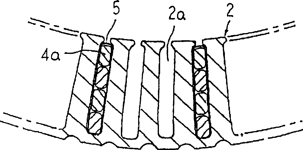
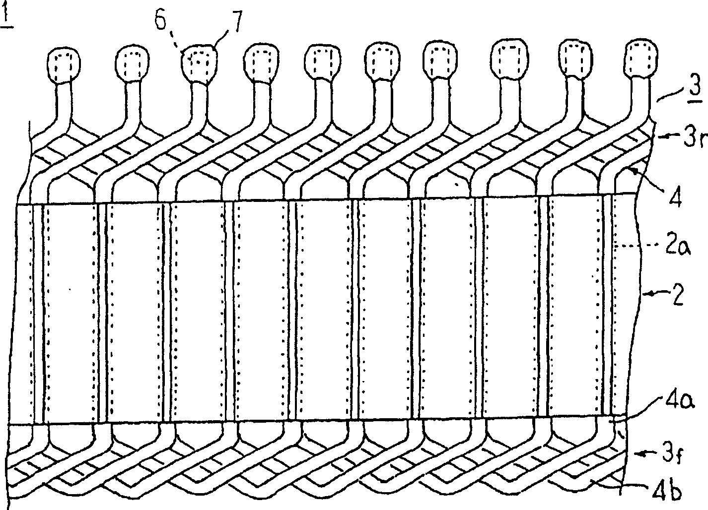
[0029] figure 1 It is a perspective view showing main parts of the stator of the rotary electric machine according to Embodiment 1 of the present invention, figure 2 It is a cross-sectional view showing main parts of the stator of the rotary electric machine according to Embodiment 1 of the present invention, image 3 It is a plan view of main parts of the stator of the rotary electric machine according to Embodiment 1 of the present invention viewed from the inner diameter side, Figure 4 A cross-sectional view illustrating the insulation structure of the joint portion of the stator winding in the stator of the rotary electric machine according to Embodiment 1 of the present invention, Figure 5 for Figure 4 The V-V cross-sectional view of the Figure 6 It is a perspective view for explaining a conductor portion suitable for a stator winding in a stator of a rotary electric machine according to Embodiment 1 of the present invention. Also, for the sake of illustration, ...
Embodiment 2
[0058] Figure 8 A cross-sectional view illustrating the insulation structure of the stator winding in the stator of the rotary electric machine according to Embodiment 2 of the present invention, Figure 9 for Figure 8 The IX-IX direction view sectional view.
[0059] In Example 2, the insulating layer 7A adopts a two-layer structure of a first insulating layer 8A made of epoxy resin and a second insulating layer 9A made of silicone resin, as shown in Figure 8 and Figure 9 As shown, the first insulating layer 8A covers each joint portion 6 (area melted and integrated), and coats and forms a form spanning the joint portions 6 adjacent in the radial direction and the circumferential direction, and the second insulating layer 9A covers The first insulating layer 8A and the insulating coating-removed regions of the respective end portions 4c are covered and coated to form a form spanning the joint portion 6 and the first insulating layer 8A adjacent in the radial and circum...
Embodiment 3
[0065] In Embodiments 1 and 2 above, the U-shaped conductor portion 4 is used as a wire bundle to constitute the stator winding 3 , but in Embodiment 3, the stator winding 16 is formed using the continuous conductor wire 30 as a wire bundle.
[0066] Figure 10 It is a perspective view showing a stator of a rotary electric machine according to Embodiment 3 of the present invention, Figure 11 It is a perspective view showing a state in which the cover body of the stator of the rotary electric machine according to Embodiment 3 of the present invention is not installed, Figure 12 It is an end view showing the periphery of the attached connecting wire part when the cover body of the stator of the rotary electric machine according to Embodiment 3 of the present invention is not installed when viewed from the axially outer side, Figure 13 It is an end view schematically showing a phase winding of the stator winding in the stator of the rotary electric machine according to Embodi...
PUM
| Property | Measurement | Unit |
|---|---|---|
| thermal conductivity | aaaaa | aaaaa |
| thermal conductivity | aaaaa | aaaaa |
Abstract
Description
Claims
Application Information
 - R&D
- Intellectual Property
- Life Sciences
- Materials
- Tech Scout
- Unparalleled Data Quality
- Higher Quality Content
- 60% Fewer Hallucinations
Browse by: Latest US Patents, China's latest patents, Technical Efficacy Thesaurus, Application Domain, Technology Topic, Popular Technical Reports.
© 2025 PatSnap. All rights reserved.Legal|Privacy policy|Modern Slavery Act Transparency Statement|Sitemap|About US| Contact US: help@patsnap.com


