
A tool dedicated for build-up welding of magnetic medium

A welding tool and magnetic medium technology, which is applied in the field of tools in the production of magnetic medium surfacing welding, can solve problems such as distortion, high production cost, and increased processing volume.

Inactive Publication Date: 2009-07-01
GUANGZHOU RES INST OF NON FERROUS METALS
View PDF3 Cites 0 Cited by
  • Summary
  • Abstract
  • Description
  • Claims
  • Application Information

AI Technical Summary

Problems solved by technology

Thousands of rods are to be welded between two upper and lower thin steel plates (after the stainless steel rod passes through the stainless steel thin plate, the protruding length can be determined according to the welding process), and the strength of the welded joint after welding is close to the performance of the base metal; The welding methods are compared repeatedly, and the MIG semi-automatic welding process is ideal. During the welding process of multiple stainless steel sheets and thousands of round bars, due to their own small binding force, the stress is easy to release during welding, and the interval between each weld seam is very small. (1 ~ 10mm, which is the same as on a thin plate from beginning to end, continuously), resulting in large deformation; the previous method is to fix the unformed magnetic medium on a platform in a simple way, and then, first Welding the upper part, because the upper stainless steel sheet is not completely fixed, after the first few welds are welded, the deformation of the stainless steel sheet is quite obvious (1 ~ 5mm), causing some stainless steel rods to separate from the stainless steel sheet, and the welding process cannot be completed , even if the stainless steel rod and the stainless steel sheet are not separated, the final welding deformation is relatively large (generating overall distortion); first, the magnetic medium welding may fail, product quality cannot be guaranteed, and the production cost is high; second, it may be due to excessive deformation Roughly increases the amount of follow-up processing, which also increases the production cost;

Method used


Image

  • A tool dedicated for build-up welding of magnetic medium
  • A tool dedicated for build-up welding of magnetic medium
  • A tool dedicated for build-up welding of magnetic medium

Examples


Embodiment Construction

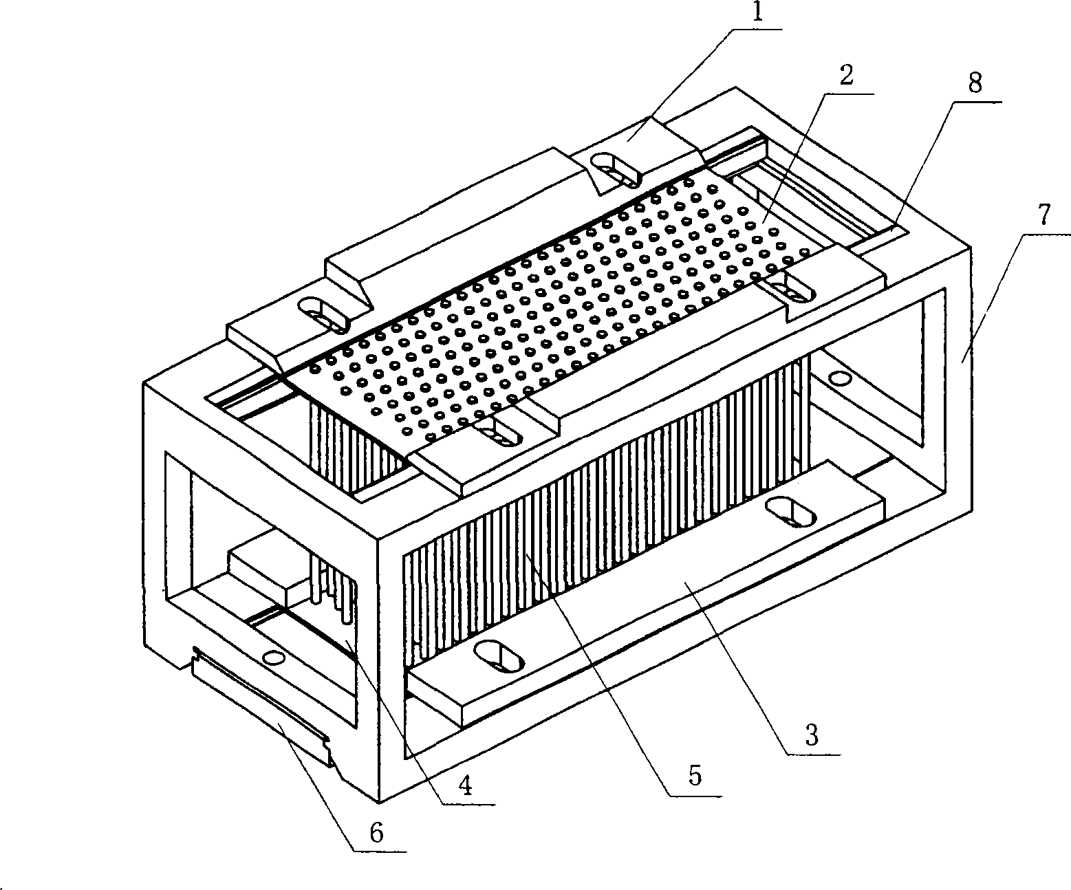
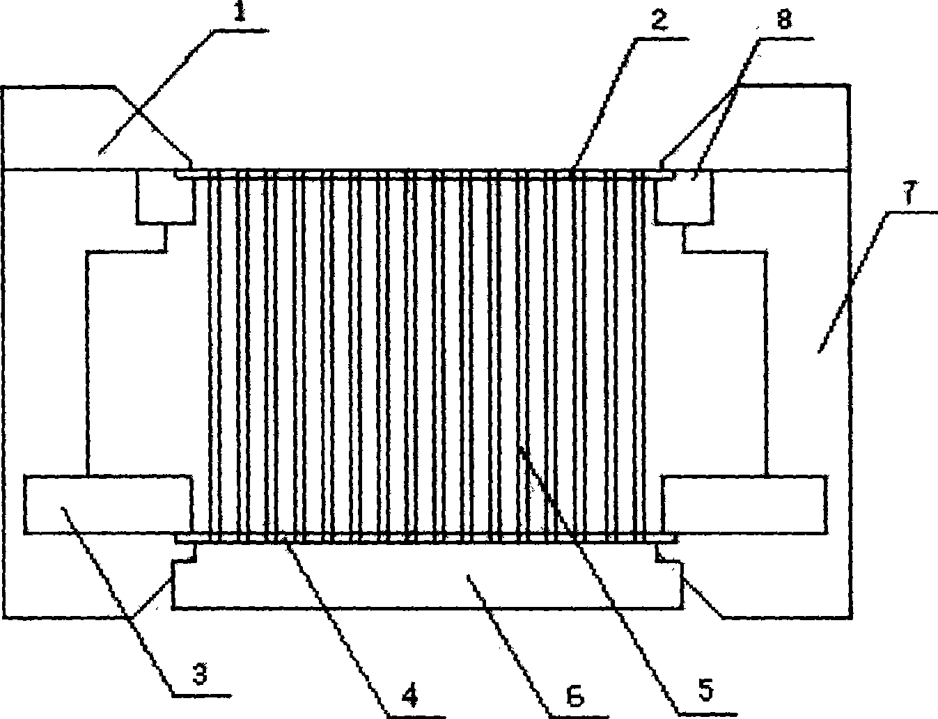
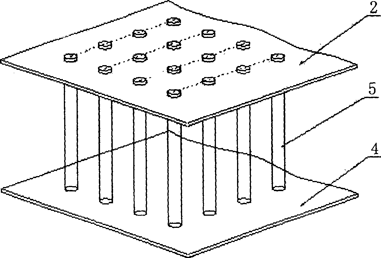
[0010] like Figure 1 to Figure 2 As shown, the magnetic medium build-up welding tool of the present invention comprises frame 7, lower bracket 6, lower pressing block 3, upper bracket 8, upper pressing block 1, wherein frame 7 middle part is provided with can accommodate such as image 3 As shown in the cavity of the magnetic medium stack, the lower bracket 6 is slidably installed on the bottom of the frame 7 to support the lower stainless steel plate 4 of the magnetic medium stack and prevent each medium rod 5 from slipping through the perforation of the lower stainless steel plate 4 Out, the lower pressing block 3 is detachably installed on both sides of the bottom plate of the frame 7 through bolts, and is used to embed the two sides of the lower stainless steel plate 4 of the magnetic medium stack to avoid deformation of the lower stainless steel plate during the welding process; the upper support The block 8 is installed on both sides of the upper part of the cavity groo...


PUM


Abstract

A magnetic medium stack welding tool includes a frame, a lower support block, a lower pressure block, an upper support block, and an upper pressure block, wherein a cavity groove for accommodating a magnetic medium stack is arranged in the middle of the frame, and the lower support block is slidable It is installed at the bottom of the rack, and the lower pressing blocks are detachably installed on the bottom plates on both sides of the rack; the upper supporting blocks are installed on both sides of the upper part of the rack cavity, and the upper pressing blocks are detachably installed on the top plates on both sides of the rack. superior. Since the invention adopts the structure of the magnetic medium stacking welding tool composed of the detachable upper and lower support blocks, the upper and lower pressing blocks and the frame organically combined, the upper and lower stainless steel plates can be clamped reliably and stably so that the upper and lower stainless steel plates can be clamped in the welding process. There will be no deformation during the welding process, and the medium rod of the magnetic medium stack is in a free state during the welding process, so that it can be easily inserted into the fine holes of each stainless steel plate, and at the same time, it is very convenient and simple to install and disassemble. flexibility to achieve the purpose of the present invention.

Description

technical field [0001] The invention relates to the field of metallurgical beneficiation, in particular to a tool in the production of magnetic medium surfacing welding in a beneficiation machine. Background technique [0002] The magnetic medium in the mineral processing machine can be composed of thousands of metal rods densely embedded between two positioning thin plates according to certain rules. The size of the rods in the magnetic medium is Φ1~Φ4 (length: 60-550mm), such as Figure 1 , Finally, the magnetic medium after welding must maintain a certain squareness (deformation ≤ 3 ~ 5mm). Thousands of rods are to be welded between two upper and lower thin steel plates (after the stainless steel rod passes through the stainless steel thin plate, the protruding length can be determined according to the welding process), and the strength of the welded joint after welding is close to the performance of the base metal; The welding methods are compared repeatedly, and the MIG...

Claims


Application Information

Patent Timeline
Patent Type & Authority Patents(China)
IPC IPC(8): B23K37/04B23K37/053
Inventor 何健全赵明王威汤玉和谢继满王丽娟
Owner GUANGZHOU RES INST OF NON FERROUS METALS
Learn More