
Latch needle

A technology of latch needles and latches, applied in the field of latch needles, which can solve the problems of hindering the function of latch needles, dust and fluff cannot be removed, and latch spring blockage, etc., to achieve the effect of smooth passage

Inactive Publication Date: 2009-07-01
GROZ BECKERT KG
View PDF4 Cites 0 Cited by
  • Summary
  • Abstract
  • Description
  • Claims
  • Application Information

AI Technical Summary

Problems solved by technology

However, the latch spring largely blocks this passage
As a result, especially dust and fluff generated during the processing of hairy yarns cannot be easily removed from the latch seam
Dust tends to collect in the latch seam at the top of the latch needle and eventually prevents the regular function of the latch needle

Method used


Image

  • Latch needle
  • Latch needle
  • Latch needle

Examples


Embodiment Construction

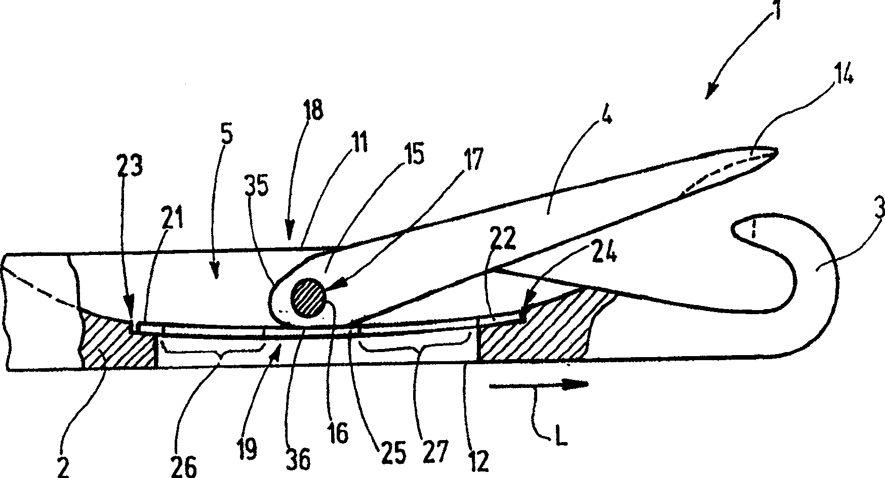
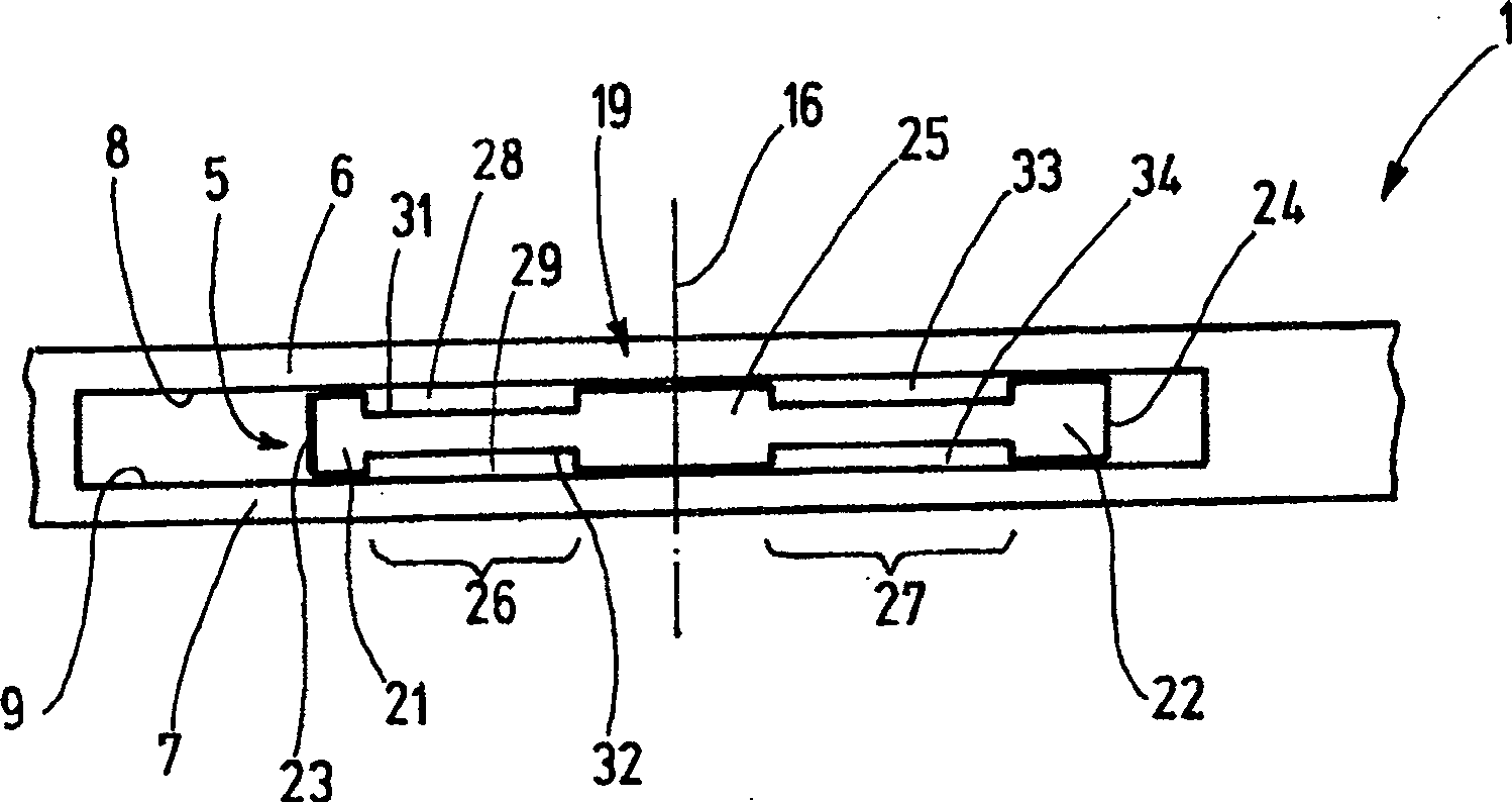
[0027] figure 1 A latch needle 1 is shown having a handle 2 , a hook 3 and a latch 4 arranged thereon. as from figure 2 As seen in the figure, the shank 2 has a latch seam 5, and the seam walls 6, 7 of the latch seam 5 have horizontal inner surfaces 8, 9 facing each other. The latch seam 5 forms a passage which ends at the latch needle side plate 11 and at the latch needle back 12 .

[0028] The latch 4 and its latch spoon 14 can rest on the tip of the hook 3 in the first position, and in the second position can be turned away from the hook 3 to the maximum, extending into the latch seam together with its latch shank end 15 5 in. The support pin 16 extends transversely with respect to the shank 2 through the latter and passes through the latch shank end 15 at a latch hole 17 . The needle latch shank end 15 forms a needle latch support device 18 together with the handle hole 17 and the support pin 16, and the needle latch support device 18 is used as a rotating support for...


PUM


Abstract

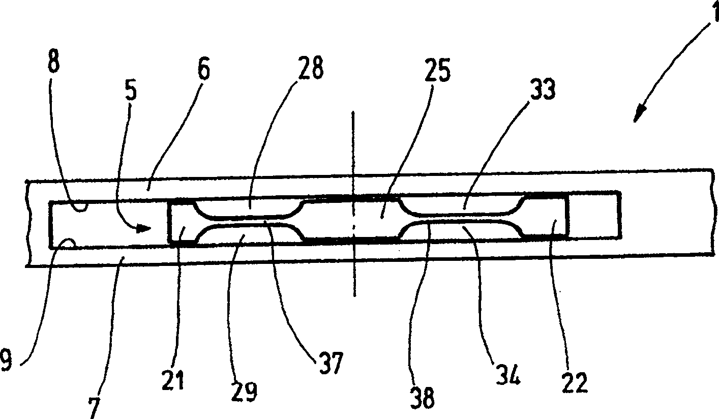
A latch needle (1) has a latch spring (19), and the width of the latch seam (5) adopted by the latch spring (19) is close to the latch support device (18). However, the latch spring (19) is narrower on both sides of this section (25). By means of this, premature wear of the latch or spring in this section of the latch carrier device (18) is reduced on the one hand, and on the other hand the latch seam (5) is blocked by dust or dirt . The narrower sections (26, 27) of the latch spring (19) together with the inner faces (8, 9) of the slit walls (6, 7) form a passage through which foreign objects, such as fibrous residues, dust Wait. The upper latch needle side (11) can be fed out in the direction towards the latch needle back (12). In contrast to conventional latch needles, a latch needle ( 1 ) of this design reduces wear, reduces susceptibility to soiling and thus increases reliability.

Description

technical field [0001] The invention relates to a latch needle for a knitting machine. Background technique [0002] A latch needle of a knitting machine is known from DE-AS 11 13537, the latch of which is rotatably situated in the latch slot and is in contact with a leaf spring arranged in the latch slot. The leaf spring is used to set a defined rotational position via a detent position. [0003] The latch spring bears against the end of the latch located in the latch seam. If the latch is turned, the end of the latch rubs against the latch spring. This often leads to wear of the material of the needle latch and the leaf spring, wherein the leaf spring may slowly bite into the end of the needle latch. Since this wear of the material may occur in an indeterminate one-sided and point-like manner, the leaf spring may have a tendency to tilt, which negatively affects the ability of the latch needle to function. [0004] Usually, the latch seam forms a passage that is open t...

Claims


Application Information

Patent Timeline
Patent Type & Authority Patents(China)
IPC IPC(8): D04B35/04
CPCD04B35/04
Inventor 王志勇
Owner GROZ BECKERT KG
Learn More