Light-emitting assembly circuit framework and liquid crystal display

A technology of liquid crystal display and light-emitting components, which is applied in the direction of circuits, static indicators, instruments, etc., and can solve the problems of widening gaps, increasing the complexity of circuit layout, and degrading the uniformity of liquid crystal display screens.

Inactive Publication Date: 2009-07-01
AU OPTRONICS CORP
View PDF3 Cites 0 Cited by
  • Summary
  • Abstract
  • Description
  • Claims
  • Application Information

AI Technical Summary

Problems solved by technology

As shown in the figure, the light-emitting component circuit includes light-emitting diodes 110, 112, 114, and 116. The light-emitting component circuit is configured on a flexible circuit board (FPC) 100 carrying light-emitting components. The light-emitting diodes 110 and 112 are connected in series by wires 120, and Arranged on the same side of the flexible circuit board 100 carrying the light-emitting component, the light-emitting diodes 114 and 116 are connected in series by wires 122, and are arranged on the other side of the flexible circuit board 100 carrying the light-emitting component, the wire 120 is divided into a part 120a (indicated by dotted line) and part 120b (indicated by solid line), electric wire 122 is divided into the part of 122a (indicated by dotted line) and the part (indicated by solid line) of 122b, the part of electric wire 120b and electric wire 122b is sectional view The wires that can be seen in , the wires 120b and 122b are wires that cannot be seen in the cross-sectional view, and the positive current i 2 The electric wire 120a flows through the light-emitting diode 112 and the light-emitting diode 110 in sequence, and then flows out through the electric wire 120b. The positive current i 2 The wire 122a flows through the LED 116 and the LED 114 in sequence, and then flows out through the wire 122b. Since the internal resistance of the LEDs is not the same, there may be an error value of 10-20 ohms between each LED. The component configuration circuit is easy to cause two currents i 1 and i 2 Not equal, such as the greater the difference in the internal resistance of the light-emitting diodes, the current i 1 and i 2 The gap will also become larger, which will affect the brightness of the liquid crystal display containing this kind of flexible circuit board, making the picture uniformity of the liquid crystal display worse
In addition, the positive and negative power lines of the flexible printed circuit board 100 equipped with light-emitting components are arranged in a staggered manner, which will also increase the complexity of circuit layout.

Method used


Image

  • Light-emitting assembly circuit framework and liquid crystal display
  • Light-emitting assembly circuit framework and liquid crystal display
  • Light-emitting assembly circuit framework and liquid crystal display

Examples


Embodiment Construction

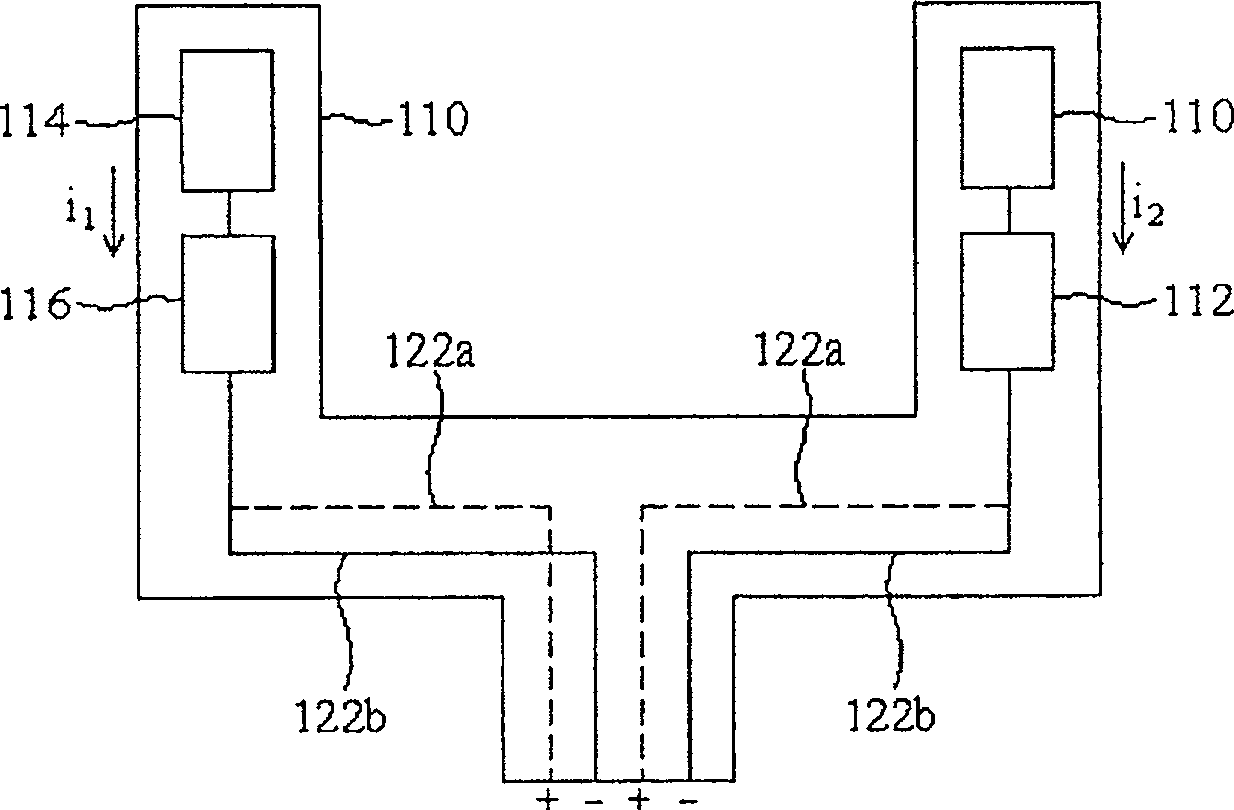
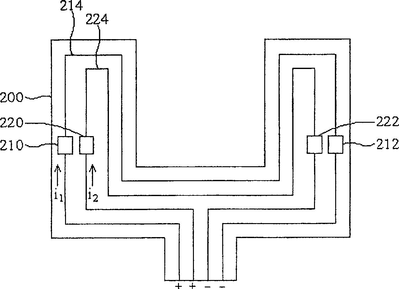
[0014] figure 2 It is a schematic cross-sectional view of the circuit structure of the light-emitting component and the flexible circuit board equipped with the light-emitting component including the circuit structure of the light-emitting component according to the first embodiment of the present invention. In this embodiment, two sets of light-emitting component circuits constitute the circuit structure, and each set of light-emitting component circuits includes two light-emitting diodes as an example for illustration. As shown in the figure, one set of light-emitting component circuits includes light-emitting diodes 210 and 212 , and the other set of light-emitting component circuits includes light-emitting diodes 220 and 222 .

[0015] The light emitting diodes 210 and 212 are connected in series by wires 214 , but the light emitting diodes 210 and 212 are disposed on different sides of the flexible circuit board 200 on which the light emitting components are mounted. Th...


PUM


Abstract

A luminous components circuit frame is used to join the luminous components in flexible printing circuit. Multiple luminous components can also form this frame, and the multiple luminous components circuit is paralleled in the flexible circuit board. Each luminous component at least first component located on the first side of flexible circuit board and second component located on the second side of flexible circuit board. The input current is on first side and through first and second luminous components and is outputted from second side.

Description

technical field [0001] The present invention relates to a configuration circuit of a light-emitting component, in particular to a circuit structure of a light-emitting component configured on a flexible circuit board (Floppy Printed Circuit: hereinafter referred to as FPC), and a liquid crystal display module including the flexible circuit board. Background technique [0002] figure 1 It is a cross-sectional schematic diagram of an existing light-emitting component circuit and a flexible circuit board configured with the light-emitting component circuit. As shown in the figure, the light-emitting component circuit includes light-emitting diodes 110, 112, 114, and 116. The light-emitting component circuit is configured on a flexible circuit board (FPC) 100 carrying light-emitting components. The light-emitting diodes 110 and 112 are connected in series by wires 120, and Arranged on the same side of the flexible circuit board 100 carrying the light-emitting component, the lig...

Claims


Application Information

Patent Timeline
Patent Type & Authority Patents(China)
IPC IPC(8): G02F1/133G02F1/1345G02F1/13357H01L33/00
Inventor 周贤颖施鸿民
Owner AU OPTRONICS CORP
Why Eureka
Try Eureka