

Impeller or agitator type full-automatic washing machine
A fully automatic washing machine and stirring technology, which is applied to other washing machines, washing machines with containers, washing devices, etc., can solve the problems of increased resonance frequency, reduced system quality, and complicated manufacturing of suspension systems, so as to ensure quality, reduce costs, and reduce costs. The effect of reducing the transport weight
- Summary
- Abstract
- Description
- Claims
- Application Information
AI Technical Summary
Problems solved by technology
Method used
Image

Examples
no. 1 Embodiment
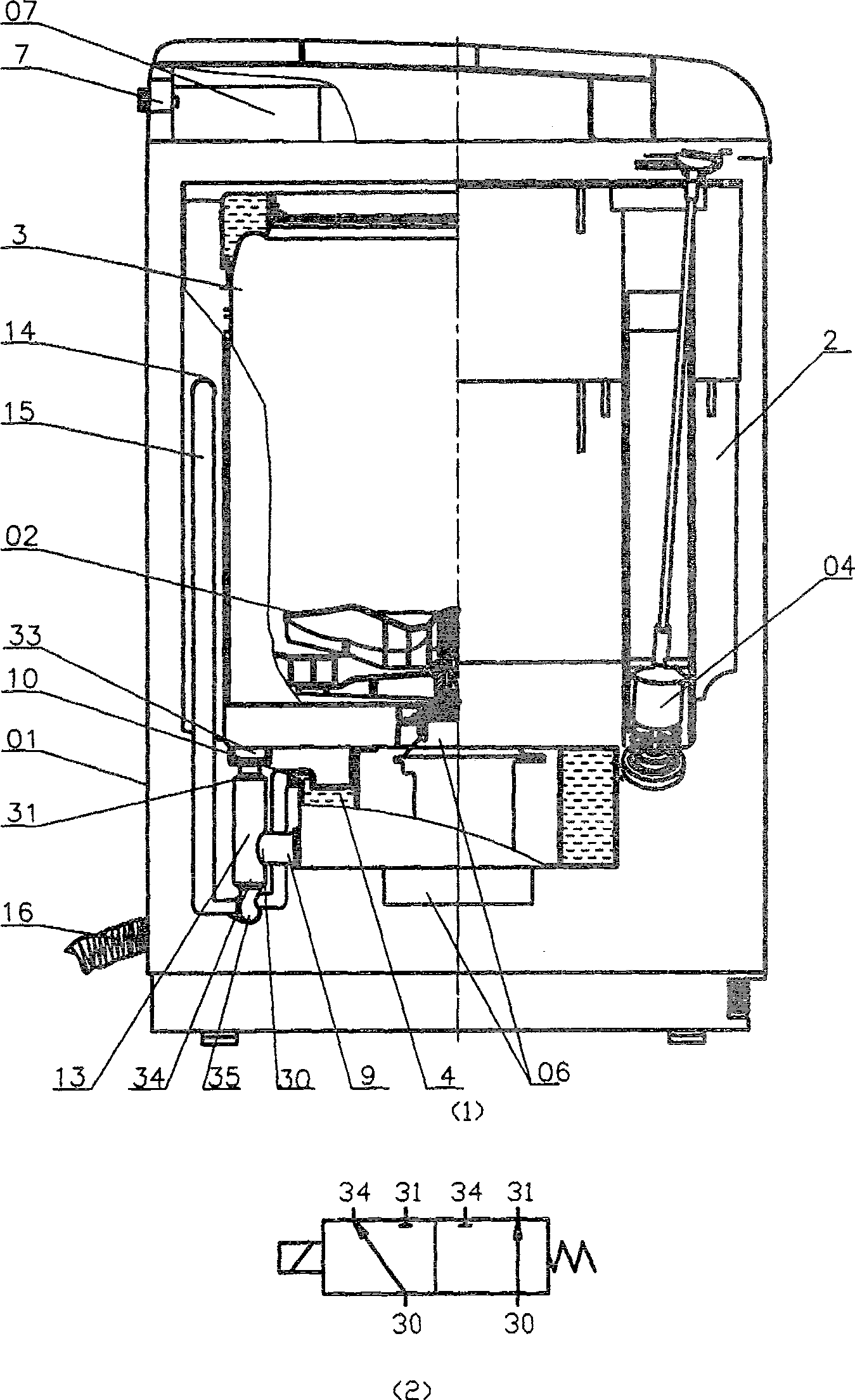
[0025] The washing machine of the first embodiment of the present invention is as figure 1 As shown: the water tub 2 is freely rotatably provided with a washing and dehydrating bucket 3 with a pulsator 02 rotatably provided at the inner bottom; it is hung in the outer casing 01 of the washing machine by the suspension part 04; the automatic controller controls the An integrated direct-drive motor—a deceleration clutch 06 is set at the center of the bottom of the water tank 2, and transmits power to the pulsator 02 and the washing and dehydrating bucket 3; the automatic controller controls the water injected by the water inlet solenoid valve 7 to pass through the water distributor 07 is sprinkled into the washing and dehydrating bucket 3; the bucket 2 is provided with a drain valve 13 at the bottom, and an overflow port 14 is provided at the top; the downstream of the drain valve 13 is connected to the overflow port 14 of the bucket through a vertically upward overflow pipe 15, ...
no. 2 Embodiment
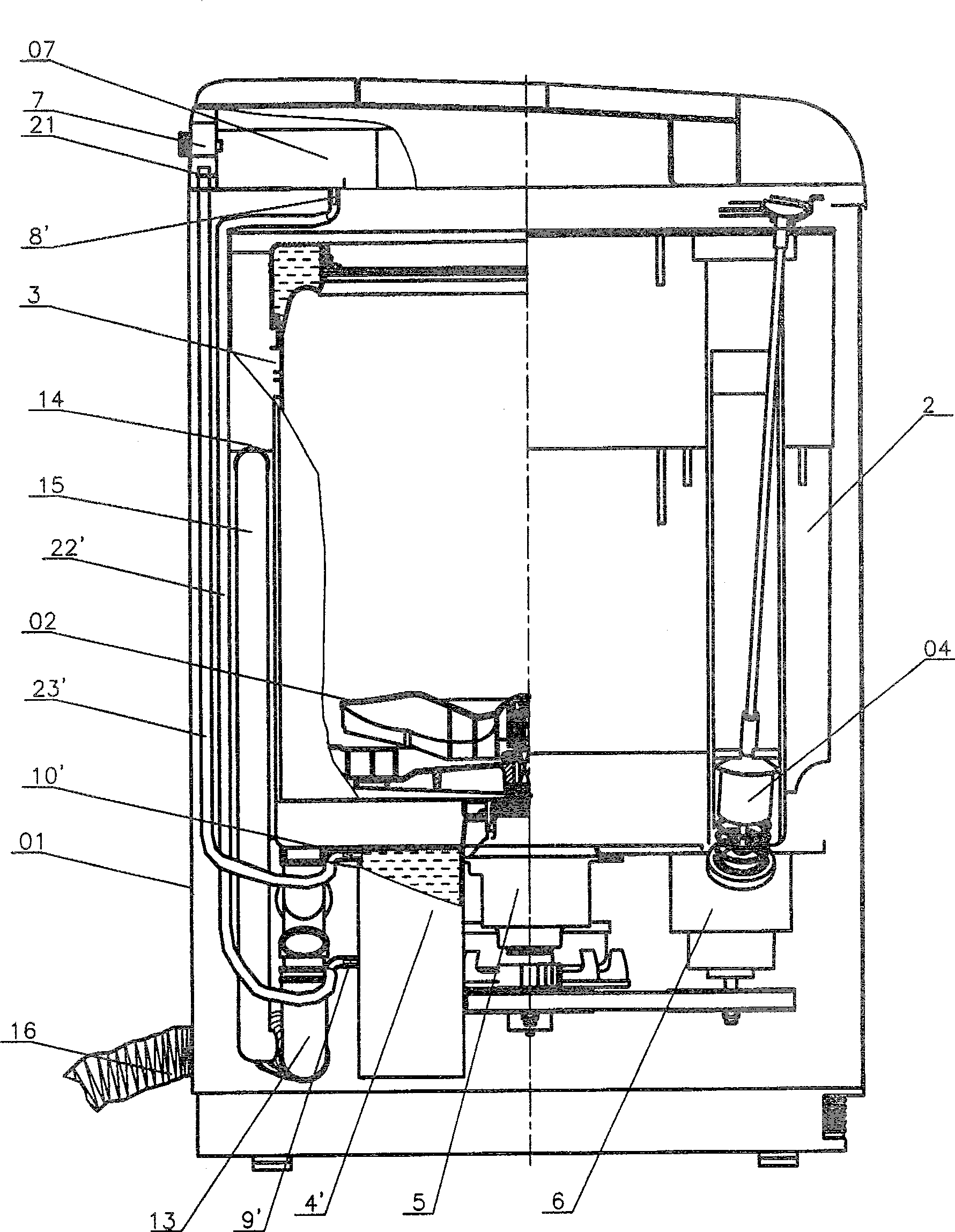
[0035] The washing machine of the second embodiment of the present invention is as image 3 shown. The washing machine has the typical constitution of another pulsator type fully automatic washing machine in the prior art. Its difference with the typical composition of the prior art pulsator type fully automatic washing machine described in the first embodiment is only: the automatic controller controls the power transmission to the pulsator 02 and the washing and dehydration bucket 3 is located at A belt transmission mechanism formed by the deceleration clutch 5 at the center of the bottom of the bucket 2 and the motor 6 on one side.
[0036] The 2nd embodiment washing machine of the present invention is to make following improvement on the basis of such prior art washing machine, see image 3 :
[0037] ——The bottom of the water bucket 2 is combined with a nearly cubic cavity 4' on the other symmetrical side of the motor 6. The cavity 4' can also be processed as an indepe...
no. 3 Embodiment
[0044] The washing machine of the third embodiment of the present invention is as Figure 4 shown. The washing machine is a typical structure of the prior art pulsator-type fully automatic washing machine described in Embodiment 1 or Embodiment 2 of the present invention, and the chamber for filling water can be the chamber in the form of Embodiment 1 or Embodiment 2, On the basis of the above, the following improvements are made, see Figure 4 :
[0045] - The chamber 4 or 4' is provided with a water injection hole 9" at its lower part and an exhaust overflow hole 10" at its top corner;
[0046] - The water outlet of the solenoid valve 7 is provided with a diversion hole 8";
[0047] ——The overflow pipe 15 is provided with an overflow hole 17 at a height higher than the exhaust overflow hole 10" and lower than the diversion hole 8";
[0048] ——The pipe 22" is connected to the water injection hole 9" and the diversion hole 8"; the hose 23" is connected to the exhaust overf...
PUM
 Abstract
Description
Claims
Application Information