Supercharge Your Innovation With Domain-Expert AI Agents!

Radiating system of light-emitting diode

A technology for light-emitting diodes and heat dissipation systems, which is applied to semiconductor/solid-state device components, semiconductor devices, electrical components, etc., and can solve problems such as deficiencies

Inactive Publication Date: 2009-07-22
HUIZHOU BYD IND
View PDF5 Cites 0 Cited by
  • Summary
  • Abstract
  • Description
  • Claims
  • Application Information

AI Technical Summary

Problems solved by technology

Such as Chinese Patent No. 200420034088.0, this patent discloses a LED heat dissipation structure, that is, a metal sheet is placed inside the lamp body. Obviously, this heat dissipation method is far from enough for the heat dissipation requirements of high-power light-emitting diodes.

Method used


Image

  • Radiating system of light-emitting diode
  • Radiating system of light-emitting diode
  • Radiating system of light-emitting diode

Examples


no. 2 approach

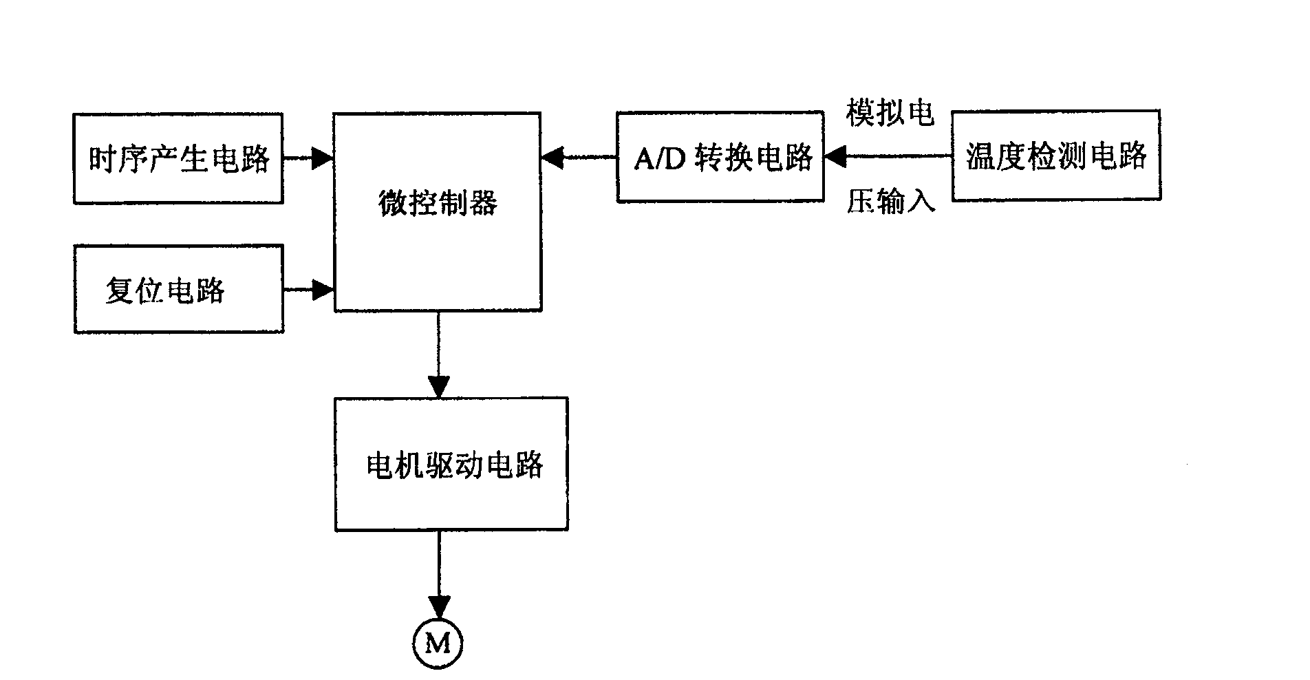
[0039] see Image 6 , other circuit parts are the same as the first embodiment, wherein the motor drive circuit is changed to a second control chip IC3 specially used for motor drive, wherein the first terminal and the fourth terminal of IC3 are output terminals, and are connected with the motor Connected, the second terminal and the third terminal are integrated circuit working voltage terminals, the fifth terminal and the eighth terminal are connected to the analog ground, the sixth terminal and the seventh terminal are logic variable input terminals, respectively connected to the first A control chip IC1 has a fifteenth connection terminal and a sixteenth connection terminal.

[0040] The working mode of the second control chip IC3 is as follows: the sixth terminal and the seventh terminal are logic variable input terminals, the first terminal and the fourth terminal are output terminals, and the logic relationship is as follows: when the sixth terminal inputs a high level ...


PUM


Abstract

The invention relates to a heat radiating system used in high-power light emitting diode, wherein it comprises liquid-cold radiator and controller; said radiator is formed by liquid cooling head, cooling tower, duct, cooling liquid tank, and water pump at the bottom of diode; the duct connects the cooling head, cooling tower, cooling liquid tank, and water pump; the water pump is connected to one motor; the controller is connected to motor to control ist operation; when the bottom temperature T of diode is higher than tH, motor works until the temperature T is lower tL; the values of tH and tL are set in controller.

Description

technical field [0001] The invention relates to a heat dissipation system suitable for high-power light-emitting diodes, in particular to a heat dissipation system of light-emitting diodes with good heat dissipation effect. Background technique [0002] At present, the heat dissipation problem of high-power light-emitting diodes (hereinafter referred to as LEDs) for lighting has always been the most troublesome matter in the industry. The solution is to increase the area of ​​the heat dissipation substrate, or to improve the shape of the heat dissipation substrate and use better heat dissipation materials. Such as Chinese Patent No. 200420034088.0, this patent discloses a LED heat dissipation structure, that is, a metal sheet is placed inside the lamp body. Obviously, this heat dissipation method is far from enough for the heat dissipation requirements of high-power light-emitting diodes. . Contents of the invention [0003] In order to overcome the above defects, the obj...

Claims


Application Information

Patent Timeline
Patent Type & Authority Patents(China)
IPC IPC(8): H01L23/473H01L33/00H01L33/64
CPCH01L2924/0002
Inventor 王尧许波
Owner HUIZHOU BYD IND
Features
  • R&D
  • Intellectual Property
  • Life Sciences
  • Materials
  • Tech Scout
  • Unparalleled Data Quality
  • Higher Quality Content
  • 60% Fewer Hallucinations
Learn More