Control method for light field in holographic printing technology and its system

A printing technology and a control method technology, which are applied in the field of spatial periodic lattice position control method and system thereof, can solve the problems of unstable light field phase exposure effect, inability to form periodic pattern exposure map, increase in feature size, etc., and achieve high stability flexibility and controllability, reducing system complexity, reducing the effect of width

Inactive Publication Date: 2009-08-05
SUN YAT SEN UNIV
View PDF7 Cites 0 Cited by
  • Summary
  • Abstract
  • Description
  • Claims
  • Application Information

AI Technical Summary

Problems solved by technology

However, in the holographic printing process, due to the time accumulation of exposure, the instability of the light field phase has a great impact on the exposure effect, which can lead to an increase in feature size and a decrease in resolution.
For longer operation, even for the result that the periodic pattern is blurred or even impossible to form the periodic pattern exposure map

Method used


Image

  • Control method for light field in holographic printing technology and its system
  • Control method for light field in holographic printing technology and its system
  • Control method for light field in holographic printing technology and its system

Examples


Embodiment Construction

[0038] The present invention will be further described below in conjunction with the accompanying drawings.

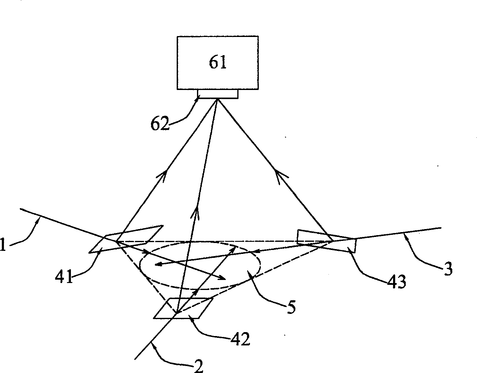
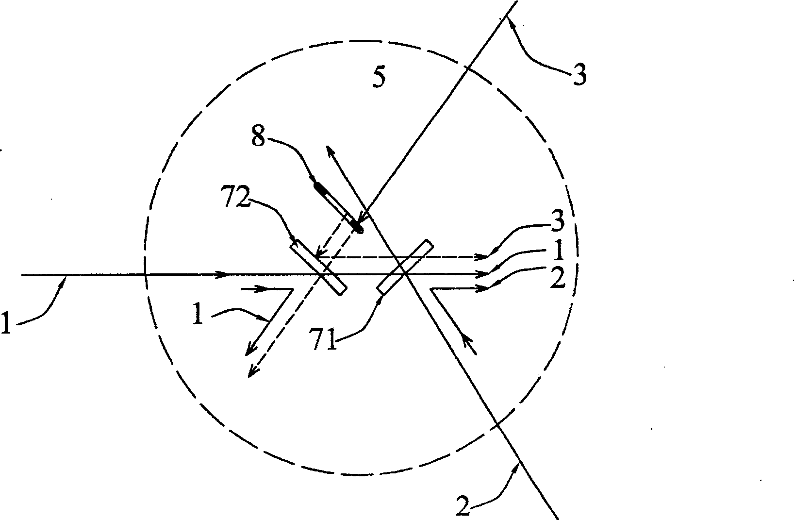
[0039] Take the holographic printing light field formed by three beams of light as an example to illustrate the present invention, the light path diagram of the light field is as follows figure 1 As shown, the three incident He-Ne lasers 1, 2 and 3 are reflected to the CCD61 by three half-mirrors 41, 42 and 43, and the three beams are not collinearly intersected, forming spatial interference at the intersection point The grid can be observed by CCD61. The present invention adopts the method of adding ccd61 to microscope 62 to recombine and amplify the light in microscope 62 and observe with ccd61, so that the effect of control can be observed conveniently and directly in real time. The three beams of light 1, 2 and 3 passing through the half-mirrors 41, 42 and 43 intersect on a plane, such as area 5 in the figure, and area 5 is the plane for realizing system control. ...


PUM


Abstract

The invention relates to the field of micro-displacement control technology in the direction of optomechanical integration and holographic plane printing technology, and aims to overcome the deficiencies in the prior art and provide a method that can effectively eliminate the influence of light field phase changes on printing effects and improve resolution. , and make it technically possible to control the change of the interference pattern by controlling the phase of the light field. The control method and system of the light field in the holographic printing technology. The system structure includes: an optical system for separating multiple beams of coherent light at any angle and adjusting the non-collinear light of two coherent lights into collinear light; for measuring the interference fringes of two collinear lights A light intensity measurement system; and a feedback control system for converting the light intensity change signal into a control signal to realize phase locking of two beams of light.

Description

technical field [0001] The invention relates to the field of optical-mechanical-electrical integration direction micro-displacement control technology and holographic plane printing technology, and relates to a space period grid position control method and a system thereof that can realize laser phase locking with nanometer precision. technical background [0002] Holographic printing technology uses photolithography technology to become one of the key technologies in the research and development of ultra-high integration, ultra-high-speed, ultra-high-frequency integrated circuits and devices. Arrays, the manufacture of solar absorbers and other fields have good application prospects, and are of great significance to the current nano-devices, nano-structure production, and research on the structural properties of photonic crystals. Encryption and other fields have been widely used. [0003] At present, integrated circuits have developed from only a few dozen devices on each...

Claims


Application Information

Patent Timeline
Patent Type & Authority Patents(China)
IPC IPC(8): G02F1/01G03F7/20G01J1/00
Inventor 周建英王自鑫谢向生
Owner SUN YAT SEN UNIV
Why Eureka
Try Eureka