Linear slide rail with detachable oil tank

A technology of linear slide rails and fuel tanks, which is applied to manufacturing tools, bearings for linear motion, large fixed members, etc., can solve the problems of troublesome work of adding fuel, stoppage of mechanism operation, limited fuel tank, etc., to improve market competitiveness and simplify Work procedure, cost reduction effect

Active Publication Date: 2009-08-19
HIWIN TECH
View PDF3 Cites 0 Cited by
  • Summary
  • Abstract
  • Description
  • Claims
  • Application Information

AI Technical Summary

Problems solved by technology

[0004] One, because the oil tank must be frequently filled with oil, the user bends down and reaches into the space between the upper surface of the slide rail and the top surface of the slider, and uses tools to add oil, which is not only unreasonable ergonomics design, and adding oil is very troublesome and time-consuming
[0005] Second, because the fuel tank is often replaced and repaired, but the fuel tank itself is equipped to slide outside the slide rail, so the lower edge of the fuel tank is slidingly connected with the slide rail. Therefore, users of conventional products still have to disassemble the entire linear system After that, the fuel tank can be removed, not only the operation of the whole mechanism is suspended, but also the operation is time-consuming and labor-intensive, which also causes a waste of the cost of the linear slide rail system
[0006] Third, the concept of disposable fuel tanks has become the mainstream of the market today, but the fuel tanks of existing products are limited by the structure in which the lower edge of the fuel tank is slidingly connected with the slide rails, so it has not been possible to adopt the design concept of disposable fuel tanks, which has also caused market competition. weakness

Method used


Image

  • Linear slide rail with detachable oil tank
  • Linear slide rail with detachable oil tank
  • Linear slide rail with detachable oil tank

Examples


Embodiment Construction

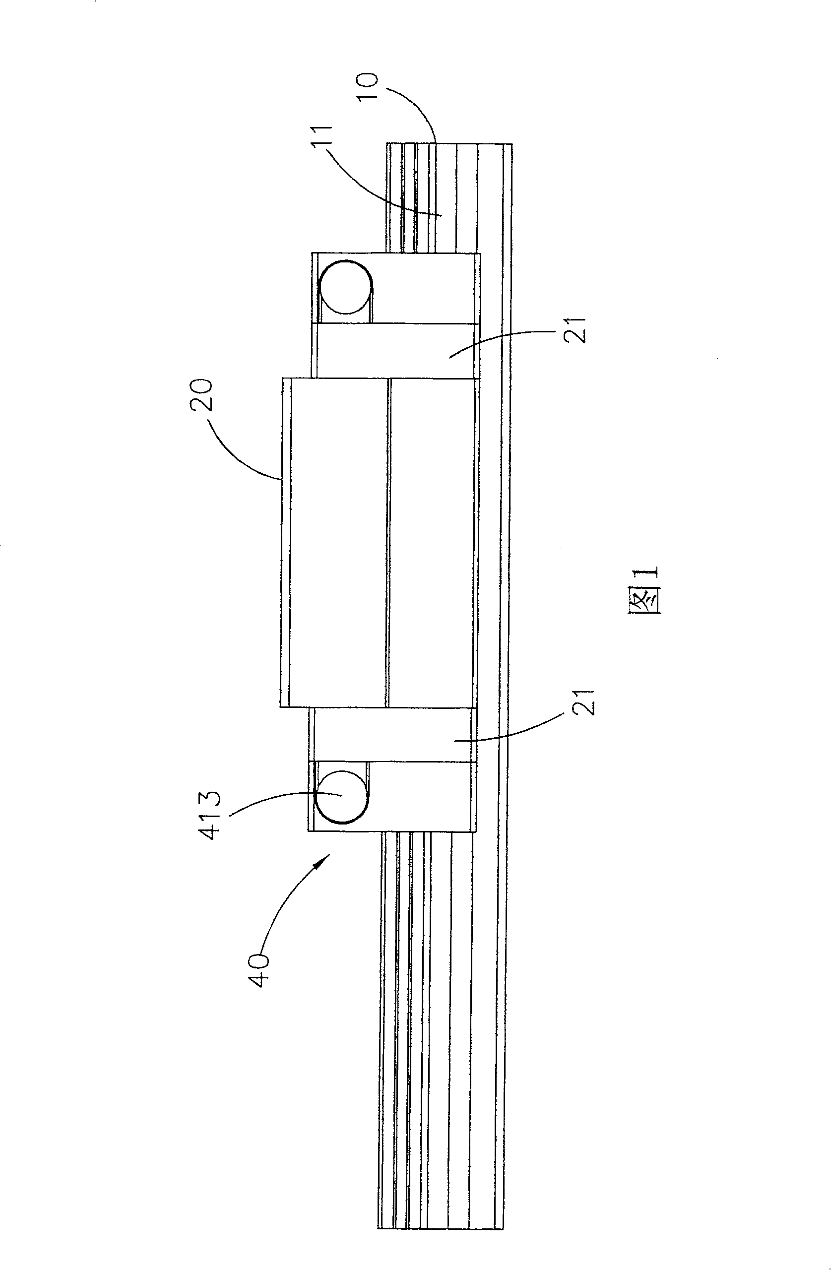
[0042] Relating to the present invention to achieve the above-mentioned purpose, the highly technical thinking and means adopted, hereby enumerate a preferred embodiment and cooperate with each drawing in detail as follows, believe that the purpose, characteristics and other advantages of the invention of the present case should be obtained by it For in-depth and specific understanding, please refer to Figure 1-7 shown.

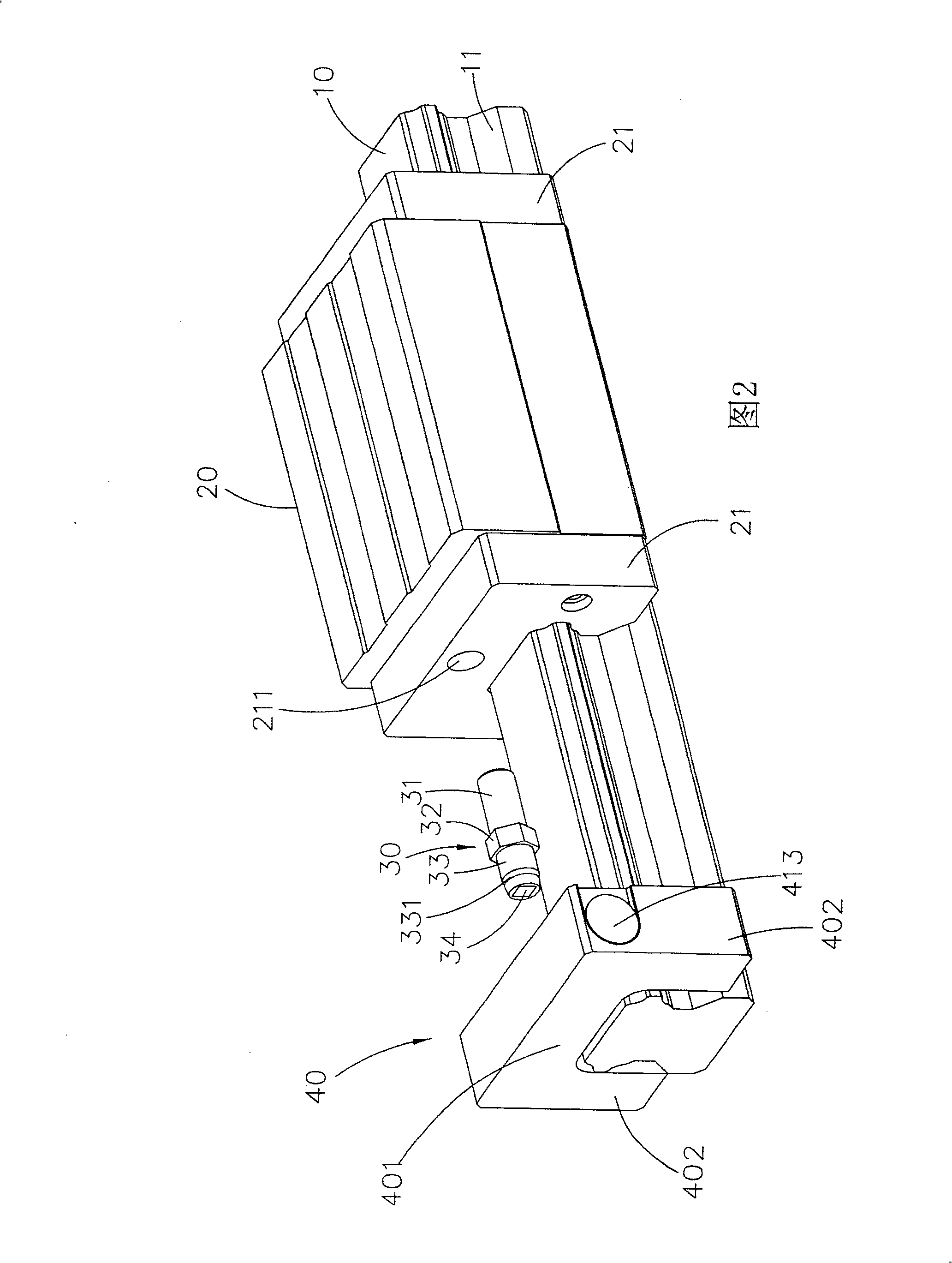
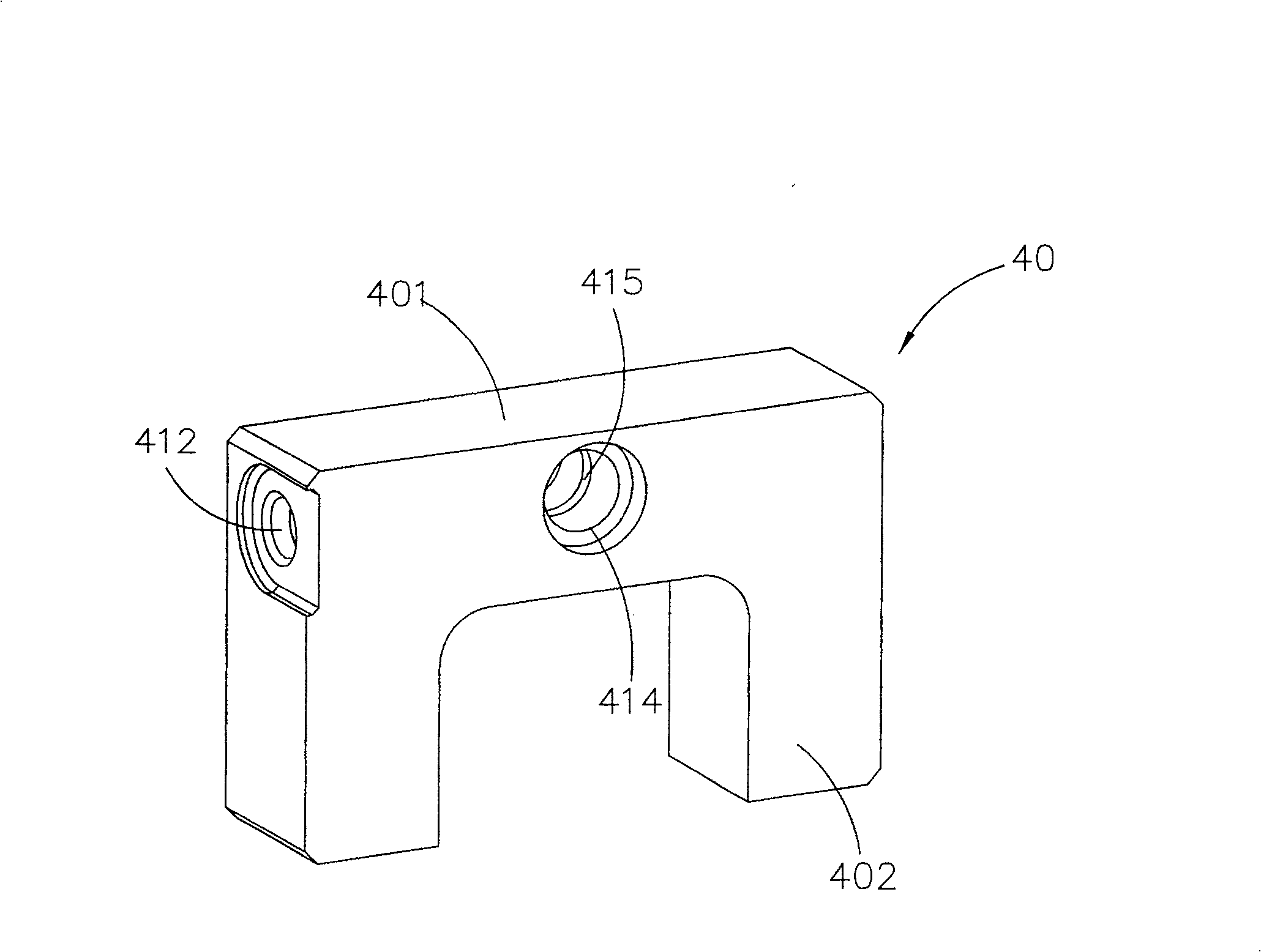
[0043] The linear slide rail with removable fuel tank of the present invention comprises a slide rail 10, a slider 20, two connectors 30 and two fuel tanks 40, and its structure is described in detail as follows:

[0044] The slide rail 10 is provided with concave-convex track structures 11 on both sides.

[0045] The slider 20 is equipped with end caps 21 at both ends, and the slider 20 and the end caps 21 are all arranged on the track structure 11 of the slide rail 10, and the end surface of the end cap 21 is provided with a threaded connection. seat 211...


PUM


Abstract

The present invention is a brand-new linear slide rail with removable fuel tank, which is specially equipped with a removable fuel tank outside the end cover, the removable fuel tank is ㄇ-shaped with two extending feet, and the inner edge of the removable fuel tank is The width of the two extended feet of the removable oil tank is greater than the maximum width of the sliding rail, and the maximum width of the ㄇ-shaped body part of the removable oil tank is smaller than the distance between the upper surface of the sliding rail and the top surface of the slider In this way, the present invention can utilize the space between the upper surface of the slide rail and the top surface of the slider to directly carry out the dismantling and replacement work of the fuel tank, and cooperate with the screwless assembly design to shorten the working hours of dismantling and replacing the fuel tank and simplify the working procedures At the same time, the cost of assembly and maintenance is greatly reduced.

Description

technical field [0001] The present invention provides a brand-new linear component system, which is specially equipped with an oil tank that can be directly replaced outside the linear component system, and can use the space between the upper surface of the slide rail and the top surface of the slider to directly carry out the replacement work . Background technique [0002] Nowadays, various precision feed systems are constantly being developed and improved. Various precision linear mechanism products have been widely used in human life, processing plants and high-tech equipment. Although the development of linear slide rail technology is very rapid, consumer use Those who still need the industry's technology to continuously improve product performance, so there are many problems that linear products (such as: linear slide rails) still need to be further developed, and related technology industries are also actively developing various technologies that can effectively impro...

Claims


Application Information

Patent Timeline
Patent Type & Authority Patents(China)
IPC IPC(8): B23Q1/01F16C29/06
Inventor 许新村谢敏耀
Owner HIWIN TECH
Why Eureka
Try Eureka