
Method for sampling, controlling and transmitting data synchronously

A data transmission method and synchronous sampling technology, applied in signal transmission systems, electrical signal transmission systems, instruments, etc., can solve the problems of occupying channel resources, accuracy cannot be guaranteed, sensitivity reduction, etc., and achieve high data transmission rate and real-time performance. Good and reliable effect

Active Publication Date: 2009-08-19
NANJING PANENG TECHNOLOGY DEVELOPMENT CO LTD
View PDF6 Cites 0 Cited by
  • Summary
  • Abstract
  • Description
  • Claims
  • Application Information

AI Technical Summary

Problems solved by technology

[0009] 1. The sampling data correction method and the sampling time adjustment method are based on the consistency of the two-way channels. For the two-way inconsistency of the channel, the calculated channel delay will have errors. When the protection fails in the zone, the sensitivity will decrease, and an out-of-zone fault will occur. may cause malfunction when
[0010] 2. After the synchronization fails in the clock correction method, re-synchronization needs to repeatedly calculate the relative error Δt of the clocks on both sides, and the synchronization delay is long, which affects the protection reaction time
[0012] 4. The sampling data correction method, the sampling time adjustment method and the clock correction method need additional time information to calculate the channel delay while sending the current sampling data, and also occupy a large amount of channel resources
[0013] 5. The GPS synchronization method is restricted by factors such as the natural environment and social environment, and requires corresponding hardware support
[0014] 6. The reference phasor synchronization method is affected by transmission line parameters and electrical quantity measurement errors, and its accuracy cannot be guaranteed

Method used


Image

  • Method for sampling, controlling and transmitting data synchronously
  • Method for sampling, controlling and transmitting data synchronously
  • Method for sampling, controlling and transmitting data synchronously

Examples


Embodiment Construction

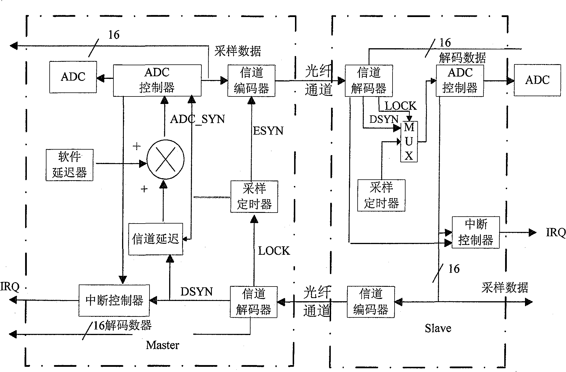
[0032] 1. The system has a master-slave structure, the master side samples regularly, and the slave side is controlled by the master side and returns the sampling data. In the figure, ADC_SYN is the main-side ADC start signal, and ESYN is the channel encoder start data transmission pulse. DSYN outputs a synchronization signal for the channel decoder. The slave uses the make signal to start the ADC and the master uses ESYN and DSYN to calculate the signal delay. LOCK is that the decoder receives valid encoded data and locks it.

[0033] 2. Signal encoding and decoding

[0034] Invention using such as figure 2 Channel coding scheme for sampling synchronization and data transmission:

[0035] figure 2 Channel Coding Diagram

[0036] t h -- synchronization signal t f --Sync frame width t 0 --logic 0 encoding t 1 --logic 1 encoding

[0037] T--symbol width T s -- sync time

[0038] The encoded high level contains information, two consecutive widths t h (=3 / 4T) indic...


PUM


Abstract

The method comprises: using FPGA or CPLD to control the A / D sampling; setting up synchronous sampling control signals; the synchronous sampling signals are outputted from the channel decoder; the sampling signals are attached with the synchronous control signals by the channel encoder, and then are sent to the decode at opposite side to realize the restore of synchronous signals and the data decode. For a system with a master / slave structure, the master machine side periodically makes sampling, and the slave machine side is controlled by the master machine side and returns the sampling data; the data sampling and the channel encode approach of data transmission use synchronous and two-way transmission, and the transmission pulse of the channel encoder has the output synchronous signals; the slave machine uses said signals to start the data sampling and the data transmission.

Description

1. Technical field [0001] The present invention relates to the synchronous sampling method of data quantity, especially to the synchronous sampling control and data transmission method of power system data quantity decoding and related relay protection method and device, more specifically, the present invention relates to based on FPGA (CPLD) Simultaneous sampling control and data transfer methods. 2. Background technology [0002] At present, various measurement, control and protection devices in power systems generally require synchronous sampling of AC data, which is of great significance for power system relay protection, fault judgment, and system stability analysis. Moreover, with the development of the power system, the requirements for system monitoring are getting higher and higher, and it is urgent to realize the remote synchronous sampling of the exchange data volume. In addition, the current differential protection of transmission lines has developed from the tr...

Claims


Application Information

Patent Timeline
Patent Type & Authority Patents(China)
IPC IPC(8): H02J13/00G08C19/00G08C19/16H02H7/26H02H3/32
CPCY04S40/143Y02E60/7884Y02E60/00
Inventor 庞吉耀
Owner NANJING PANENG TECHNOLOGY DEVELOPMENT CO LTD
Learn More