Hydraulic tensioner
A tensioning device and hydraulic technology, applied in the direction of transmission, belt/chain/gear, machine/engine, etc., can solve the problems of high cost and achieve the effect of reducing manufacturing cost
- Summary
- Abstract
- Description
- Claims
- Application Information
AI Technical Summary
Problems solved by technology
Method used
Image
Examples
Embodiment Construction
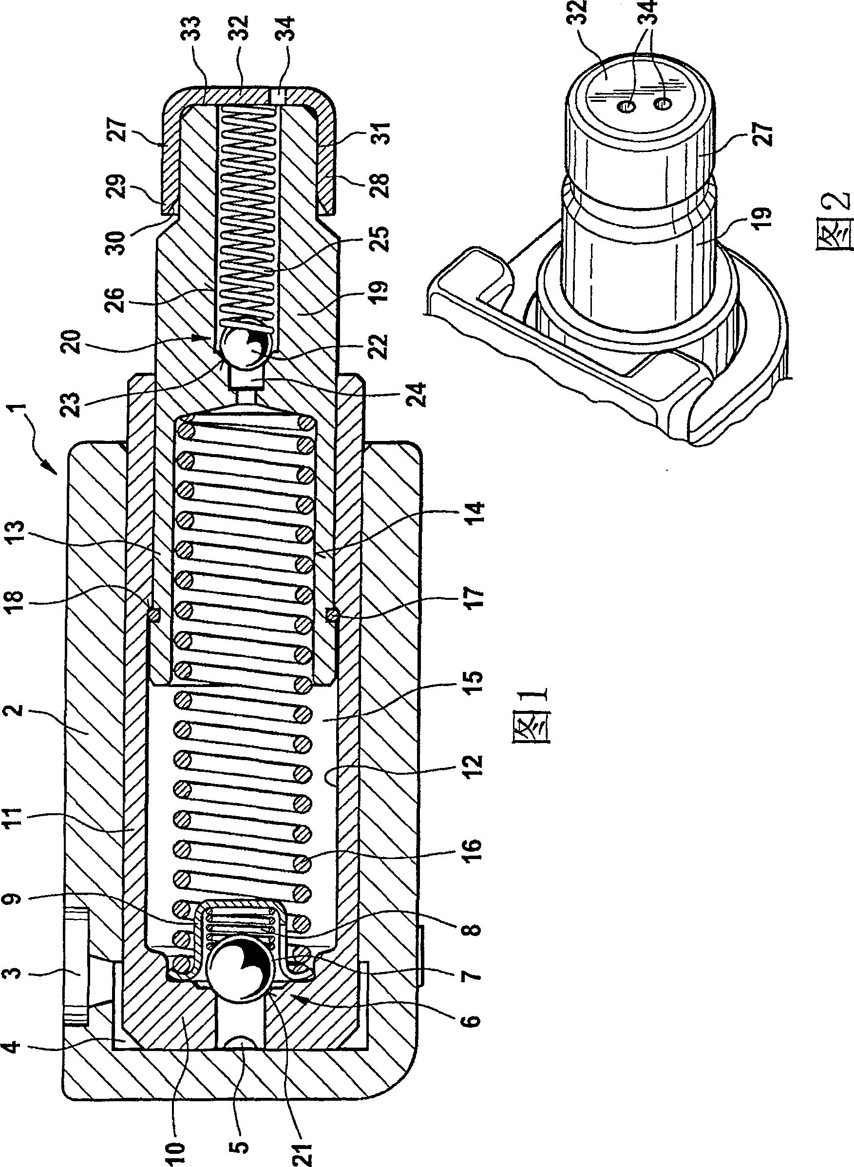
[0026] FIG. 1 shows a longitudinal section through a hydraulic tensioning device 1 with a protective housing 2 . The protective casing 2 is connected to the engine casing, not shown. It has a pressure oil port 3, and lubricating oil from the pressure oil port 3 reaches the valve 6 through the annular space 4 and the transverse groove 5. The valve 6 is located at the bottom 10 of a box 11 which is arranged in the protective case 2 with a sealing clearance. The valve 6 includes a valve ball 7 , a valve seat 21 , a valve spring 8 and a valve sleeve 9 .
[0027] The housing 11 has a blind bore 12 into which a tensioning piston 13 is introduced with sealing play. The tensioning piston 13 contains a blind bore 14 . The blind holes 12 , 14 surround a high-pressure chamber 15 in which a compression spring 16 is arranged. The compression spring 16 acts via the tensioning piston 13 on a not shown tensioning and pulling mechanism. The stroke of the tensioning piston 13 is limited by...
PUM
 Abstract
Description
Claims
Application Information
 - R&D
- Intellectual Property
- Life Sciences
- Materials
- Tech Scout
- Unparalleled Data Quality
- Higher Quality Content
- 60% Fewer Hallucinations
Browse by: Latest US Patents, China's latest patents, Technical Efficacy Thesaurus, Application Domain, Technology Topic, Popular Technical Reports.
© 2025 PatSnap. All rights reserved.Legal|Privacy policy|Modern Slavery Act Transparency Statement|Sitemap|About US| Contact US: help@patsnap.com

