Laser micro processor optical focus system

An optical focusing and laser technology, applied in optics, optical components, laser welding equipment, etc., can solve the problems of high price, high processing precision, poor processing adaptability, etc., and achieve the effect of strong adaptability and large dynamic range

Inactive Publication Date: 2009-09-02
JIANGSU UNIV
View PDF3 Cites 0 Cited by
  • Summary
  • Abstract
  • Description
  • Claims
  • Application Information

AI Technical Summary

Problems solved by technology

Herman et al. proposed to use a rotating prism to generate a non-diffraction beam, which has a simple structure, high energy utilization rate, and high energy conversion efficiency. The parameters of the non-diffraction beam generated by the rotating prism are determined, and the size of the focused spot is also determined, so the processing adaptability is poor. At the same time, due to the existence of errors, the spot of the non-diffraction beam actually produced by this system is determined in advance. Therefore, in order to obtain the spot required to meet the processing requirements, it is impossible to design and process a rotating prism that meets the requirements at one time, and the rotating prism needs to be replaced. Aspherical optical elements require high processing accuracy and are expensive, so this system still has many shortcomings.

Method used


Image

  • Laser micro processor optical focus system

Examples


Embodiment Construction

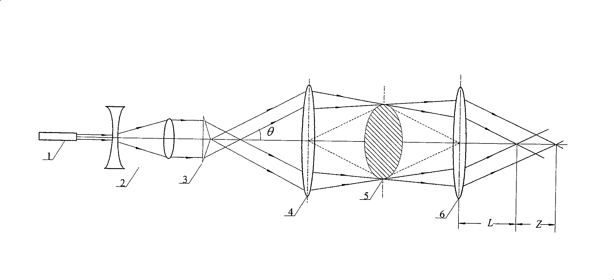
[0014] Combine below figure 1 The details and working conditions of the design method proposed by the present invention are described in detail.

[0015] The present invention comprises a laser 1, a Galileo telescope 2, a positive rotation prism 3, a first spherical lens 4 and a second spherical lens 6, the laser output beam produced by the laser 1 is expanded and collimated by the Galileo telescope 2, and then positively rotated After the transformation of prism 3, a group of conical wave vector plane waves diverging at angle θ will be generated. This group of plane waves will be focused into a thin ring at the focal plane of the image square by the first spherical lens 4, because the image square of the first spherical lens 4 The focal plane coincides with the focal plane of the object side of the second spherical lens 6, and the thin ring is transformed by the lens 6 to generate a set of cone wave vectors with an angle θ' to the Z axis. The converging area is Z, and in the ...


PUM

PropertyMeasurementUnit
diameteraaaaaaaaaa
diameteraaaaaaaaaa
refractive indexaaaaaaaaaa

Abstract

An optical focusing system for a laser micromachining machine, which relates to the fields of mechanical manufacturing and laser micromachining, and is especially suitable for applications that require a small focus spot, the size of the focus spot does not change with distance, and require zero sensitivity to workpiece position errors, and In the processing without considering the parfocal problem, it is characterized in that: two spherical lenses are placed behind the positive rotating prism, the distance from the first spherical lens to the positive rotating prism is determined according to the power of the laser, the second spherical lens and the first The spherical lens is confocal; only one rotating prism is required, and non-diffraction beams with different spot sizes can be easily produced by replacing the second spherical lens to meet different processing requirements. Low-cost ordinary spherical lenses can obtain micron-level non-diffraction beams of different sizes, which can adapt to different processing requirements.

Description

technical field [0001] The invention relates to the fields of mechanical manufacturing and laser micromachining, in particular to an optical focusing system of a laser micromachining machine, which is especially suitable for applications where the focus spot size is required to be small, the size of the focus spot does not vary with distance, and the sensitivity to workpiece position errors is required to be Zero, and there is no need to consider the parfocal problem during processing. Background technique [0002] Laser processing is one of the main directions of laser application. Due to the small heat-affected zone of laser processing, the beam directionality is good, and the light spot can be focused to the wavelength level, the processing range and depth can be accurately controlled, and it has high repeatability and Good edge, selective processing, precision processing, so it is the most competitive alternative in machining. Laser processing is an application of compr...

Claims


Application Information

Patent Timeline
Patent Type & Authority Patents(China)
IPC IPC(8): B23K26/04B23K26/06B23K26/073G02B27/00B23K26/046
Inventor 姚红兵张永康叶霞鲁金忠李国杰
Owner JIANGSU UNIV
Why Eureka
Try Eureka