Liquid-type slag releasing device of emulsifying coke mortor

A technology of liquid slag discharge and liquid slag, which is applied in the combustion of liquid fuel and gaseous fuel, the combustion of lump fuel and liquid fuel, the combustion of lump fuel and gaseous fuel, etc., which can solve the problem of insufficient emulsification. Coke slurry ash melting point, inability to emulsify coke slurry ash liquefaction, complex combustion chamber structure, etc., to achieve continuous and effective liquid slag removal, solve the problems of fire and burning ash, and reduce the generation of nitrogen oxides.

Inactive Publication Date: 2009-09-09
GUANGZHOU DEVOTION THERMAL TECH
View PDF9 Cites 0 Cited by
  • Summary
  • Abstract
  • Description
  • Claims
  • Application Information

AI Technical Summary

Problems solved by technology

It can be seen from the above analysis that, firstly, the backfired coal-water slurry liquid slagging combustion furnace is not suitable for the combustion of emulsified coke slurry; secondly, the combustion chamber temperature of the backfired coal water slurry liquid slagging combustion furnace is still low The ash melting point of the emulsified coke slurry ash cannot be reached, and the emulsified coke slurry ash cannot be liquefied; finally, the combustion chamber structure of the reverse combustion type coal-water slurry liquid slagging combustion furnace is complicated, and the manufacturing cost is high
[0008] Finally, in order to make the system operate continuously and normally, the slag receiving device at the lower part of the burner must be replaced in time, and the liquid slag also contains a large amount of waste heat that can be used. If the liquid slag is directly flowed into the slag receiving device, it will cause waste of energy

Method used


Image

  • Liquid-type slag releasing device of emulsifying coke mortor
  • Liquid-type slag releasing device of emulsifying coke mortor
  • Liquid-type slag releasing device of emulsifying coke mortor

Examples


Embodiment 1

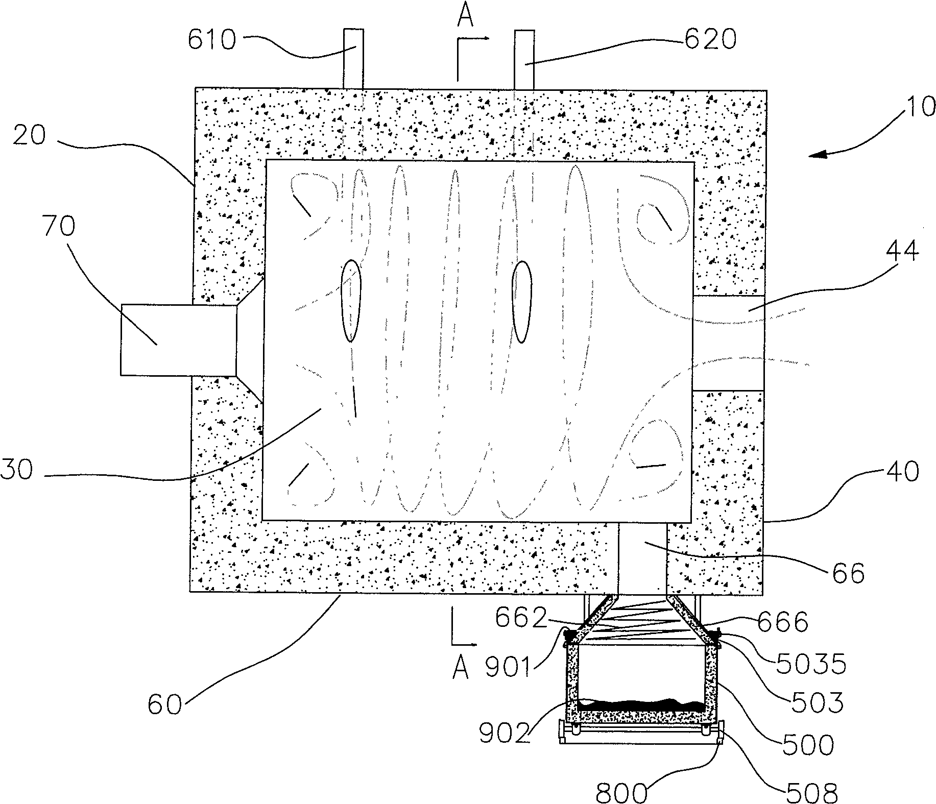
[0045] Please refer to figure 1 and figure 2 The emulsified coke slurry liquid slag discharge device of the present invention includes a housing 10, an emulsified coke slurry burner 70, an oil burner, a gas burner (not shown), and two slagging vehicles 500 (only one of which is shown in the figure) ) And guide rail 800.

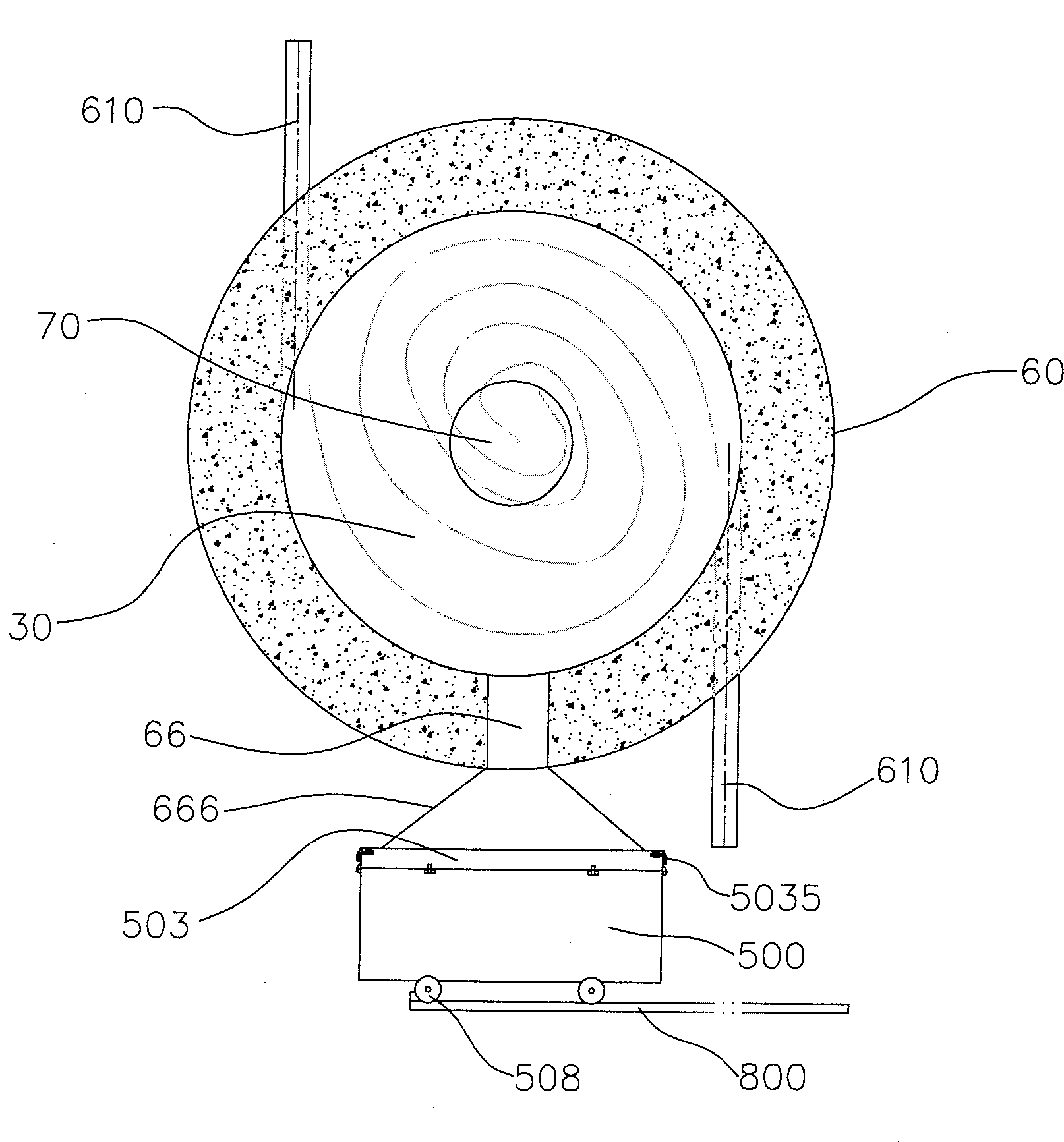
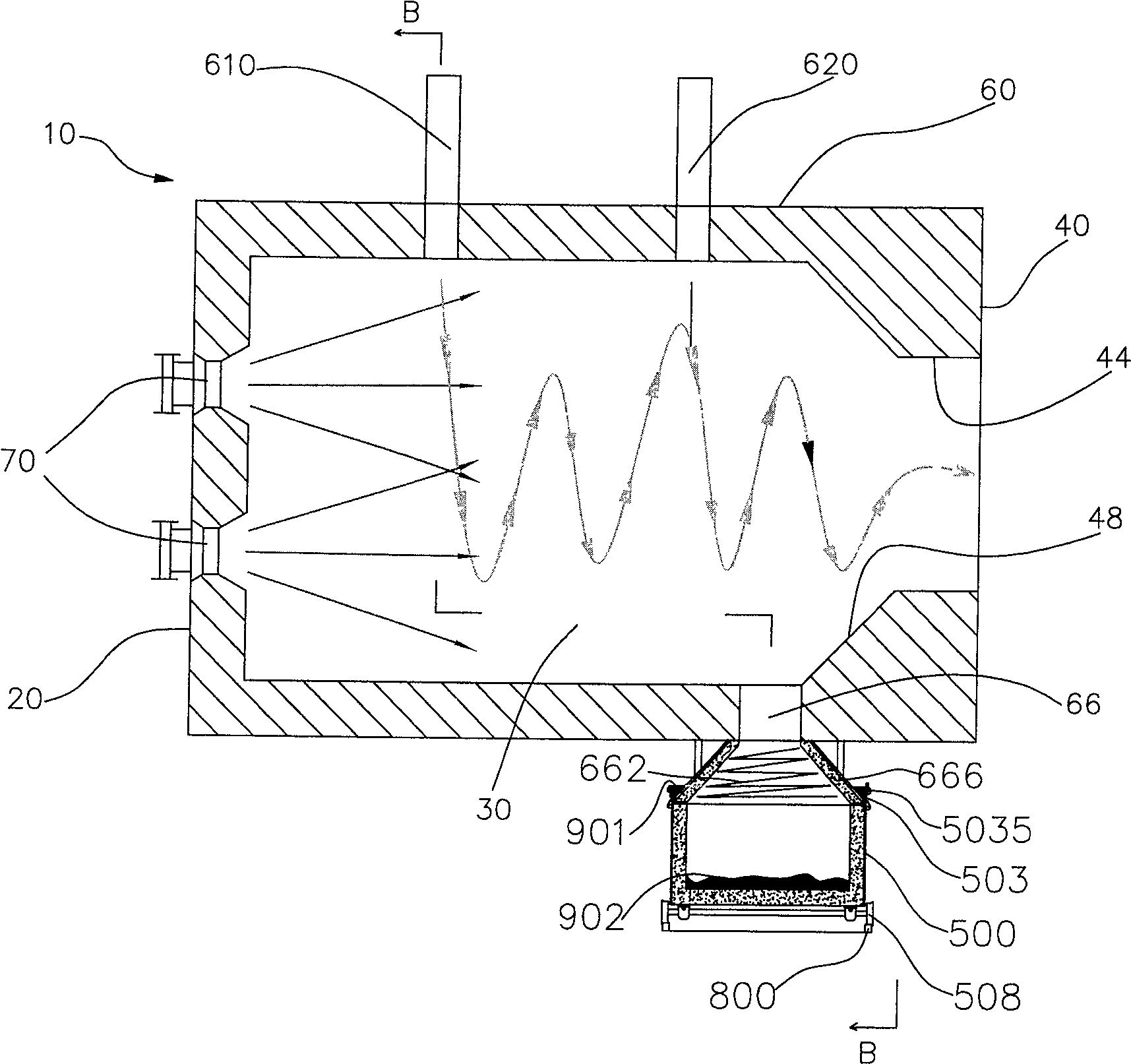
[0046]The housing 10 is surrounded by a front wall 20, a rear wall 40, and a side wall 60. The casing 10 is cylindrical, and a cylindrical combustion space 30 is formed inside the casing 10. The vertical distance between the inner wall of the rear end wall 40 and the inner wall of the front end wall 20 is 3 times the inner diameter of the combustion space 30.

[0047] An emulsified coke slurry burner 70, an oil burner and a gas burner are uniformly arranged on the front wall 20 of the housing. The emulsified coke slurry burner 70 is arranged in the center of the front wall 20, and the oil burner and gas burner are arranged in the emulsification. Below the coke ...

Embodiment 2

[0065] Please refer to image 3 and Figure 4 This embodiment is similar to embodiment 1, except that:

[0066] The opening area of ​​the liquid slag outlet 66 on the inner wall of the side wall 60 is approximately equal to one twentieth of the cross-sectional area of ​​the combustion space 30.

[0067] The vertical distance between the inner wall of the front end wall 20 and the inner wall of the rear end wall 40 is 1.5 times the inner diameter of the combustion space 30.

[0068] The diameter of the outlet 44 is approximately equal to one-half of the inner diameter of the combustion space 30, and a conical transition chamber 48 is formed between the outlet 44 and the side wall 60 of the casing 10. That is, a flared opening is formed in the rear end wall 40.

[0069] There are four emulsified coke slurry burners 70. The four emulsified coke slurry burners 70 are respectively installed on the front end wall 20 and are distributed at equal intervals on the circumference centered on ...

Embodiment 3

[0077] This embodiment is similar to Embodiment 1, except that:

[0078] The emulsified coke slurry liquid slag discharge device is provided with two spaced apart liquid slag outlets 66 of the same size, and the opening area of ​​each liquid slag outlet 66 on the inner wall of the side wall 60 is approximately equal to thirty minutes of the cross-sectional area of ​​the combustion space one.

[0079] The two liquid slag outlets 66 are surrounded by the same transition cavity 666 and connected to the slag containing space 505 of the same slag discharge truck 500.

[0080] The vertical distance between the inner wall of the rear end wall 40 and the inner wall of the front end wall 20 is 4 times the inner diameter of the combustion space 30.

[0081] The wind speed of the tangential wind delivered into the combustion space 30 by each tangential wind inlet is 28 m / s. Three sets of tangential air inlets with a total flow rate of 0.08 times the flow rate of the preheated air are arrange...


PUM


Abstract

The invention discloses a liquid slag discharge device for emulsified coke slurry, which comprises a shell surrounded by a front end wall, a rear end wall, and a side wall. A cylindrical combustion space is formed inside the shell, and the front end wall is provided with At least one emulsified coke slurry burner, and at least one oil burner and / or at least one gas burner, at least one liquid slag outlet is provided on the side wall at the bottom of the combustion space near the rear end wall, and the emulsified coke slurry is discharged in liquid state. The slag device further includes two or more slag discharge vehicles that work alternately, one of the two or more slag discharge vehicles stays below the liquid slag outlet, and the slag discharge vehicle that stays below the liquid slag outlet The slag holding space communicates with the liquid slag outlet, and the connection between the slag holding space and the liquid slag outlet is sealed. The invention adopts two or more specially designed slag discharge vehicles to work alternately, which not only ensures efficient and stable combustion of emulsified coke slurry, but also realizes continuous and effective liquid slag removal.

Description

Technical field [0001] The invention relates to a thermal equipment, in particular to a combustion slag discharge device using emulsified coke slurry as fuel. Background technique [0002] At present, the energy crisis has become a concern of people all over the world. The natural energy that can be used by mankind is becoming less and less, but the demand for energy by mankind is increasing. Therefore, all countries in the world are adjusting their energy structure to save the existing energy to the utmost extent. At the same time, environmental pollution has become the focus of attention of people all over the world in recent years. Countries all over the world are working hard to adjust the industrial structure, develop and promote clean and environmentally friendly energy with little pollution. [0003] Therefore, people are constantly seeking new clean energy. Generally, the relatively clean energy currently used by thermal equipment (such as various boiler equipment and kil...

Claims


Application Information

Patent Timeline
Patent Type & Authority Patents(China)
IPC IPC(8): F23J1/08F23C1/00F23C5/00F23C7/00F23L1/00F23D23/00F23D17/00
Inventor 常厚春李祖芹马革刘效洲
Owner GUANGZHOU DEVOTION THERMAL TECH
Why Eureka
Try Eureka