
Accuracy calibration of birefringence measurement systems

A measurement system, a technique for birefringence, applied in the field of systems of birefringence characteristics

Inactive Publication Date: 2009-09-16
HINDS INSTR
View PDF4 Cites 1 Cited by
  • Summary
  • Abstract
  • Description
  • Claims
  • Application Information

AI Technical Summary

Problems solved by technology

However, such systems require very precise assembly for accurate results

Method used


Image

  • Accuracy calibration of birefringence measurement systems
  • Accuracy calibration of birefringence measurement systems
  • Accuracy calibration of birefringence measurement systems

Examples


Embodiment Construction

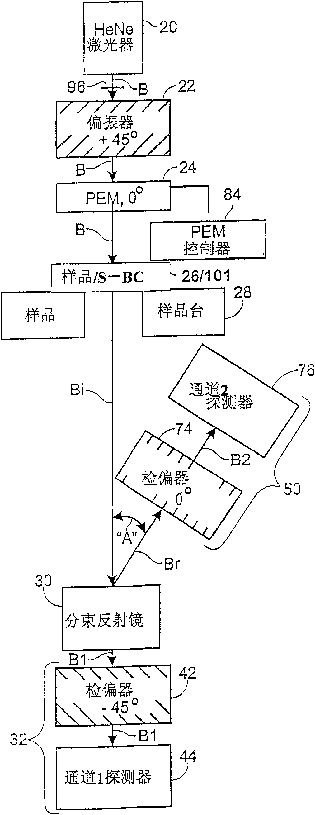
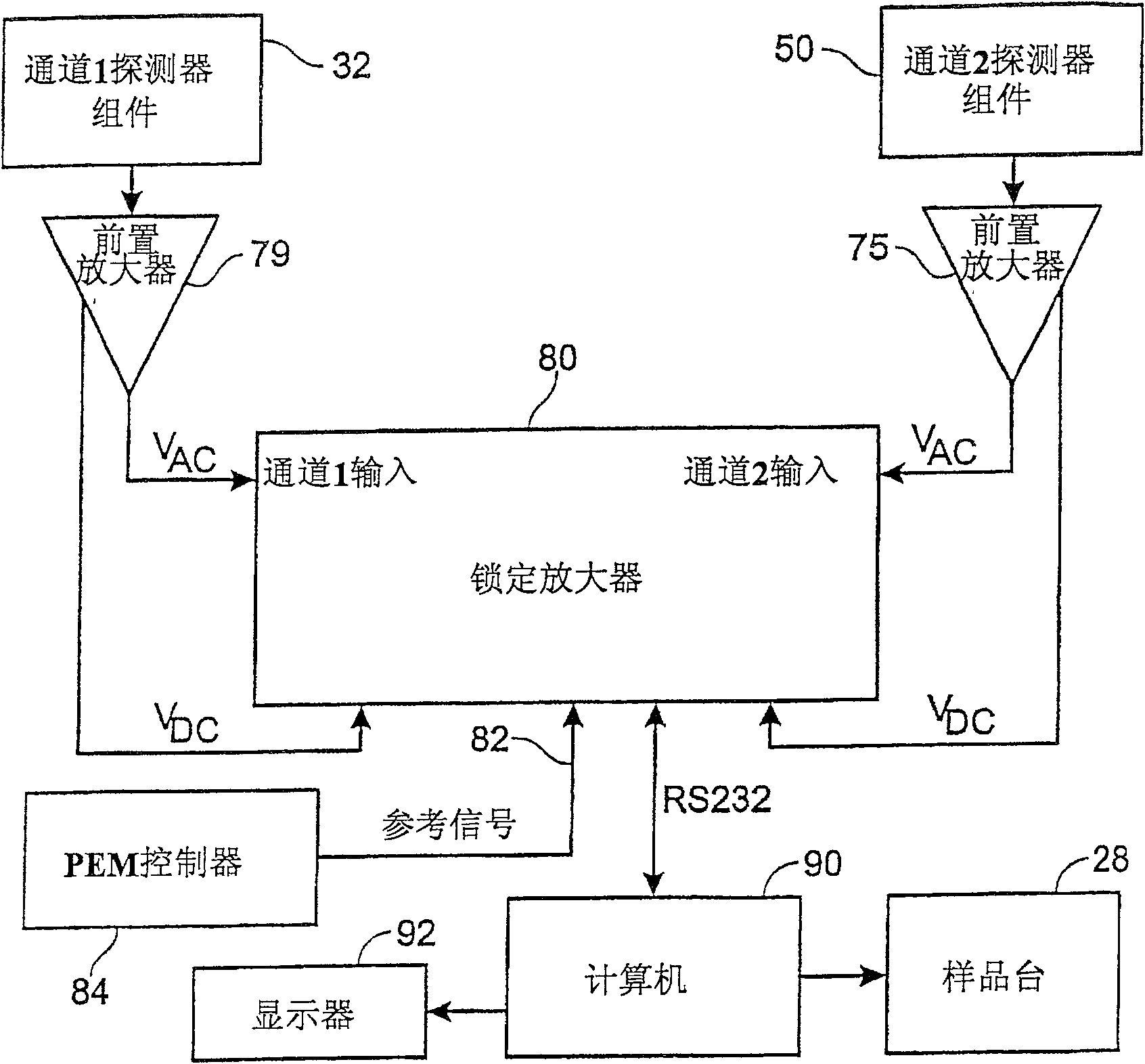
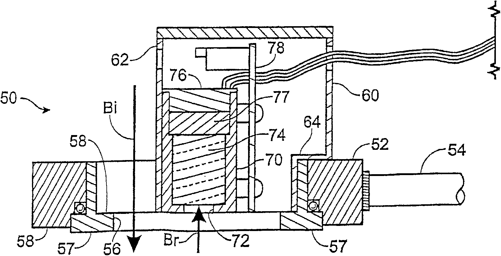
[0027] figure 1 The main optical elements of a system that can be calibrated according to the invention are described. These elements include as light source 20 a HeNe laser at a wavelength of 632.8 nanometers (nm). Beam "B" emanating along the optical path from the light source has a cross-sectional area or "spot size" of approximately 1 millimeter (mm).

[0028] Source beam "B" is directly incident on polarizer 22 whose polarization direction is oriented at +45° with respect to the baseline axis. High extinction polarizers are preferred, such as Glan-Thomson calcite polarizers. Polarizers 22 with stable precision and indexed rotators are also preferred.

[0029] The polarized light from the polarizer 22 is incident on the photoelastic modulator 24 ( figure 1 and 5 ) on the optical element 25. In a preferred embodiment, the photoelastic modulator (hereinafter "PEM") is a low birefringence version of Model PEM-90I / FS50 manufactured by Hinds Instruments, Inc., of Hillsbor...


PUM


Abstract

Systems and methods are provided for employing a Soleil-Babinet compensator (101) as a standard for calibrating a birefringence measurement system. A highly accurate and repeatable calibration can be achieved by the method described here because, among other advantages, the inventive method can calculate the different birefringence across the surface of the Soleil-Babinet compensator (101). The calibration techniques described herein can be used in birefringence measurement systems with various optics and light sources of various frequencies to measure a range of birefringence levels.

Description

[0001] This application claims as the priority date the filing date of US Provisional Patent Application No. 60 / 329,680, which is hereby incorporated by reference. technical field [0002] This application relates primarily to systems for the precise measurement of the birefringence properties of optical elements, and in particular to calibrating such systems using Soleil-Babinet compensators. Background technique [0003] Many important optical materials exhibit birefringence. Birefringence means that light of different linear polarizations travels through a material at different speeds. These different polarizations are often viewed as two mutually orthogonal components of polarized light. [0004] Birefringence is an inherent property of many optical materials and can be induced by external forces. Retardation or retardation represents the overall effect of birefringence along the propagation path of the beam in the sample. If the incident beam is linearly polarized, t...

Claims


Application Information

Patent Timeline
Patent Type & Authority Patents(China)
IPC IPC(8): G01J4/00G01J4/04G01M11/00G01N21/23
CPCG01J4/04G01N21/23
Inventor 王宝良
Owner HINDS INSTR
Learn More