Light source device and projector
A technology of a light source device and a projector, which is applied in projection devices, image reproducers using projection devices, optics, etc., and can solve problems such as the size of the optical system becoming larger
- Summary
- Abstract
- Description
- Claims
- Application Information
AI Technical Summary
Problems solved by technology
Method used
Image
Examples
Embodiment 1
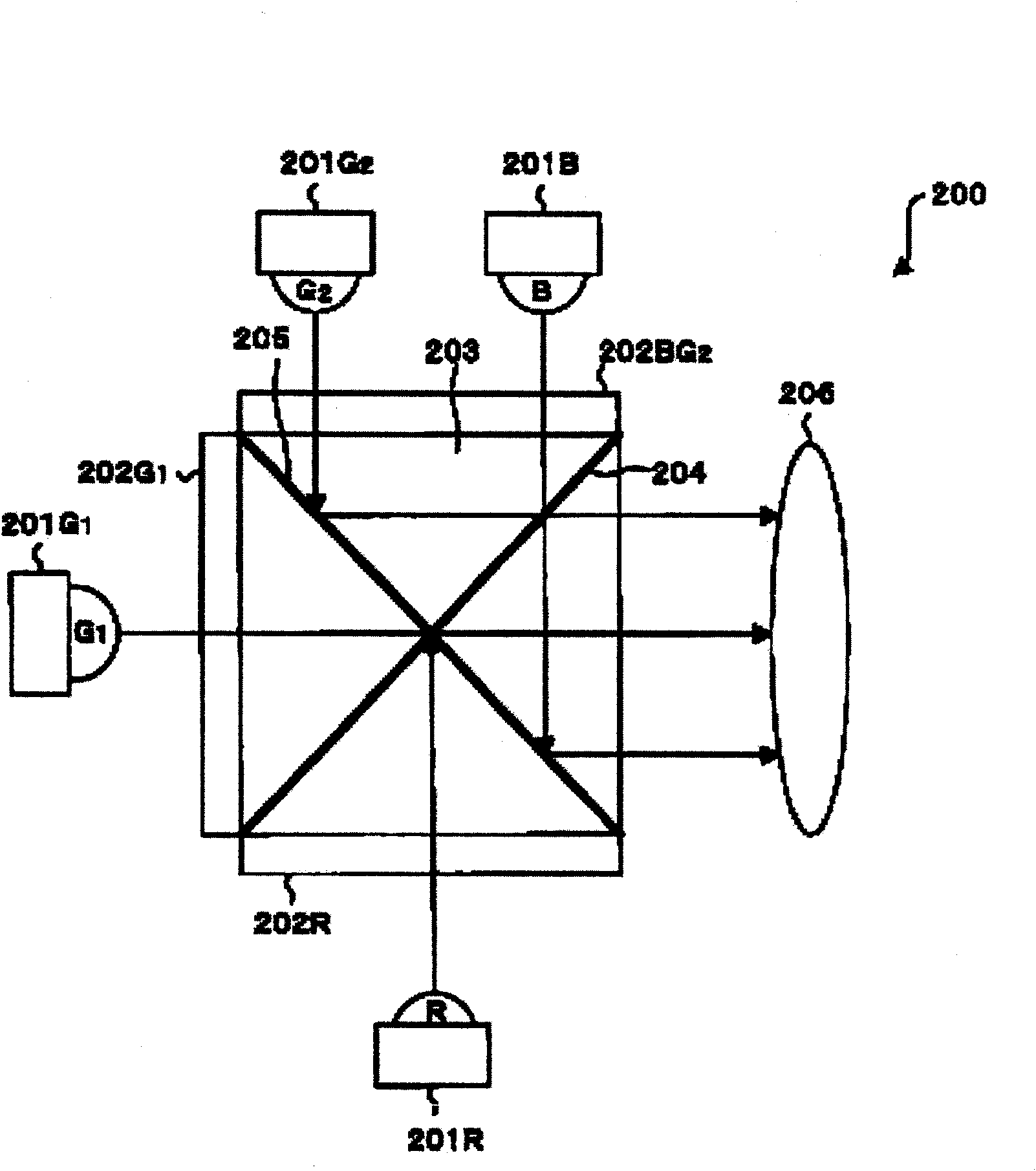
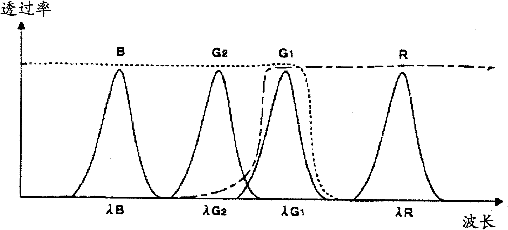
[0038] figure 1 It is a plan view showing the structure of the light source device 200 according to the first embodiment of the present invention. This light source device 200 is used, for example, in a projector. In light source device 200, LED201R, LED201G 1 , LED201G 2 and LED201B are respectively arranged in the vicinity of the three sides of the cross dichroic prism 203 described later, and generate red light (hereinafter referred to as R light) and first green light (hereinafter referred to as G light) respectively. 1 light), the second green light (hereinafter referred to as G 2 Light) and blue light (hereinafter referred to as B light) solid light-emitting elements. Among them, R light, G 1 Light, G 2 light and b light as figure 2 Shown have different peak wavelengths λR, λG 1 , λG 2 and the spectrum of λB.
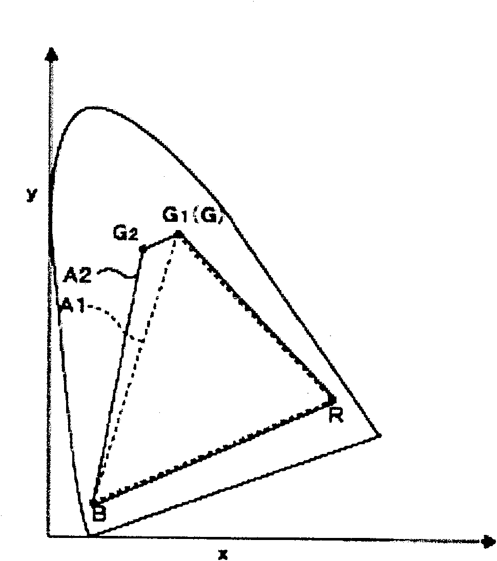
[0039] Thus, by using R light, G 1 Light, G 2 Light and B light, these 4 colors of light, such as image 3 As shown in the xy chromaticity diagram ...
Embodiment 2
[0051] In the above-mentioned embodiment 1, although the use of R light, G 1 Light, G 2 The example of the structure of the four kinds of colored light of light and B light has been described, but it can also be used as an example of adding a third green light (hereinafter referred to as G) to the above four kinds of colored light. 3 An example of the structure of the 5 shades of light). An example of such a structure will be described as Embodiment 2 below.
[0052] Figure 5 It is a plan view showing the structure of a light source device 300 according to Embodiment 2 of the present invention. The light source device 300 is used for, for example, a projector. In this figure, with figure 1 The corresponding parts of each part of the above are given the same reference numerals. In the light source device 300 shown in the figure, LED201G is added 3 , and set instead figure 1 The liquid crystal light valve 202RG shown in the liquid crystal light valve 202R 3 . LED201...
Embodiment 3
[0064] In the above-mentioned embodiment 2, although the use of R light, G 1 Light, G 2 Light, G 3 The example of the structure of the five shades of light and B light was described, but it can also be used as an example of removing G from the above five shades of light 2 An example of the structure of the 4 shades of light. An example of such a structure will be described as Embodiment 3 below.
[0065] Figure 9 It is a plan view showing the structure of a light source device 400 according to Embodiment 3 of the present invention. The light source device 400 is used for, for example, a projector. In this figure, with Figure 5 and figure 1 The corresponding parts of each part of the above are given the same reference numerals. In the light source device 400 shown in this figure, the Figure 5 LED201G shown 2 , and instead of Figure 5 The liquid crystal light valve 202BG shown 2 A liquid crystal light valve 202B is provided. The light valve 202B is arranged nea...
PUM
 Abstract
Description
Claims
Application Information
 - R&D
- Intellectual Property
- Life Sciences
- Materials
- Tech Scout
- Unparalleled Data Quality
- Higher Quality Content
- 60% Fewer Hallucinations
Browse by: Latest US Patents, China's latest patents, Technical Efficacy Thesaurus, Application Domain, Technology Topic, Popular Technical Reports.
© 2025 PatSnap. All rights reserved.Legal|Privacy policy|Modern Slavery Act Transparency Statement|Sitemap|About US| Contact US: help@patsnap.com


