Flexible cantilever plate vibration control set and control method based on acceleration sensor

An acceleration sensor, cantilever plate technology, applied in mechanical oscillation control, non-electric variable control, measurement devices and other directions, can solve the performance impact, large amount of calculation, difficult to control residual vibration and other problems

Inactive Publication Date: 2009-10-07
SOUTH CHINA UNIV OF TECH
View PDF1 Cites 0 Cited by
  • Summary
  • Abstract
  • Description
  • Claims
  • Application Information

AI Technical Summary

Problems solved by technology

[0005] (2) Since the acceleration sensor signal contains a large amount of measurement noise, the signal filtering processing based on the feedback control of the acceleration sensor is problematic; and the acceleration sensor and the piezoelectric driver are generally dislocated, which will cause different modal phase differences of each order Compensation problem, robust stability problem of closed-loop control;
[0006] (3) The compensation of nonlinear factors by the control algorithm, the suppression of fast vibrations, especially the small-amplitude residual vibrations near the equilibrium point are difficult to control; the existing control methods either have high requirements on the accuracy of the model, otherwise the performance It will be greatly affected, or the amount of calculation is large, and the actual hardware real-time implementation problem is that the real-time performance is not good
Especially based on the acceleration sensor feedback to realize the rapid vibration suppression and stability of the flexible cantilever plate, it has not been well solved

Method used


Image

  • Flexible cantilever plate vibration control set and control method based on acceleration sensor
  • Flexible cantilever plate vibration control set and control method based on acceleration sensor
  • Flexible cantilever plate vibration control set and control method based on acceleration sensor

Examples


Embodiment Construction

[0046] The present invention will be further described below in conjunction with the accompanying drawings and examples, but the protection scope of the present invention is not limited to the scope expressed by the examples.

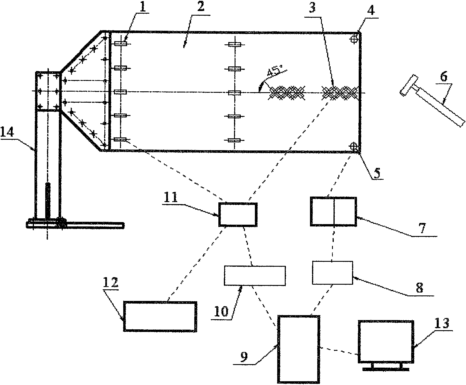
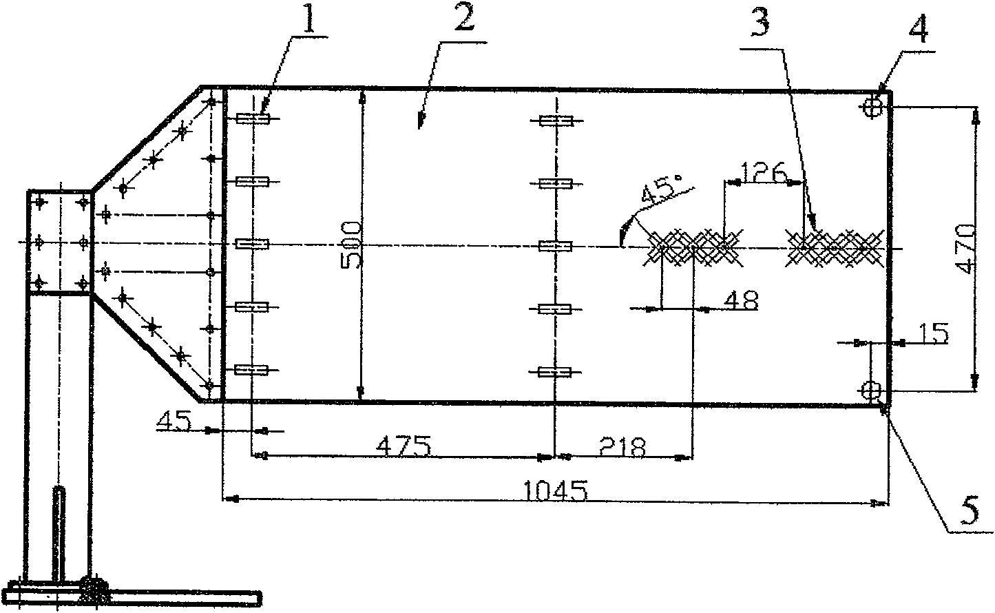
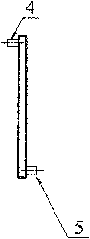
[0047] like figure 1 , 2, the vibration control device for a flexible cantilever plate based on an acceleration sensor includes a mechanical support clamping device 14, a flexible plate 2, a bending mode piezoelectric driver 1, a torsional mode driver 3, one of the acceleration sensors 4, an acceleration Sensor 2 5, extremely low frequency charge amplifier 7, multi-channel A / D conversion data acquisition card 8, computer 9, multi-channel D / A conversion card 10, multi-channel piezoelectric ceramic power supply 11, arbitrary function signal generator 12 and liquid crystal Display 13.

[0048] The clamping device 14 of the mechanical support is mainly composed of a flat rectangular base plate, a rectangular column bracket and an isosceles trapezoidal spli...


PUM


Abstract

The invention discloses a vibration control device and a control method for a flexible cantilever plate based on an acceleration sensor. The device is a plurality of piezoelectric ceramic sheets symmetrically pasted on the front and rear sides of the fixed end of the flexible plate. The double-sided polarities of the multiple piezoelectric ceramic sheets are connected in parallel to form a bending mode piezoelectric driver; The middle part is double-sided and anti-symmetrically pasted with multiple piezoelectric ceramic sheets, and the piezoelectric ceramic sheets are connected in parallel with the same polarity on both sides to form a torsional mode driver. One of the acceleration sensors and the second of the acceleration sensors are respectively installed on the free end of the flexible board Two corner positions; the device has small mass and less wiring, and only needs two acceleration sensors as sensors of the flexible cantilever plate. This method utilizes the optimal configuration of two acceleration sensors and piezoelectric drivers to realize the decoupling of the detection and drive control of the bending mode and torsional mode of the flexible cantilever plate, thereby realizing the multi-bend and multi-torsion modes of the flexible plate. The purpose of active suppression of dynamic vibration.

Description

technical field [0001] The present invention relates to vibration control of large flexible structures, in particular to a method and device for multi-mode active control of bending and torsional vibration of a space sailboard structure, and in particular to a multi-mode sensing based on multi-acceleration sensors and piezoelectric drivers. Controlled vibration control nonlinear control method and device. Background technique [0002] Large-scale complexity and flexibility are an important development trend of spacecraft structures. On the one hand, the use of large flexible accessories increases the flexibility of spacecraft design and manufacturing and reduces launch costs. On the other hand, the resulting vibration problems become more and more prominent. The modal damping of such large flexible structures is small, High-order and low-frequency intensive, especially in space sports, under the condition of environmental disturbance, its large-scale vibration will last for...

Claims


Application Information

Patent Timeline
Patent Type & Authority Patents(China)
IPC IPC(8): G05D19/02G05B13/04G01H17/00
Inventor 邱志成
Owner SOUTH CHINA UNIV OF TECH
Why Eureka
Try Eureka