Supercharge Your Innovation With Domain-Expert AI Agents!

Process for producing electrode wire for solar battery

A technology of solar cells and manufacturing methods, which is applied to circuits, photovoltaic power generation, electrical components, etc., can solve problems such as semiconductor substrates that are prone to cracks, and achieve excellent power generation efficiency and excellent conductivity

Active Publication Date: 2009-10-14
HITACHI METALS LTD
View PDF18 Cites 0 Cited by
  • Summary
  • Abstract
  • Description
  • Claims
  • Application Information

AI Technical Summary

Problems solved by technology

Therefore, when the conventional crushed wire is used as the electrode wire of the core material, there is a problem that cracks are easily generated on the semiconductor substrate during welding.

Method used


Image

  • Process for producing electrode wire for solar battery
  • Process for producing electrode wire for solar battery
  • Process for producing electrode wire for solar battery

Examples


Embodiment 1

[0040] Various clad materials having a plate thickness of 160 μm having intermediate layers of various thicknesses were produced. The above-mentioned cladding material is produced by the following method: on both sides of the intermediate layer raw material composed of an aluminum plate (material JIS 1N90, Al: 99.90mass%, annealed material) or an invar alloy plate (Fe-36.5mass% Ni, annealed material) , superimpose the surface layer raw material composed of oxygen-free copper plate (Cu: 99.97mass%, O: 15ppm, plate thickness 1.0mm, annealed material), press-bond the superimposed material at a reduction rate of 70%, and further press-bond the superimposed material at a reduction rate of 50-80%. The reduction rate of the crimping material is fine-rolled. Table 1 shows the ratio of the total reduction rate from the layered material to the cladding material and the thickness of the intermediate layer to the overall thickness of each cladding material. On the other hand, the above-m...

Embodiment 2

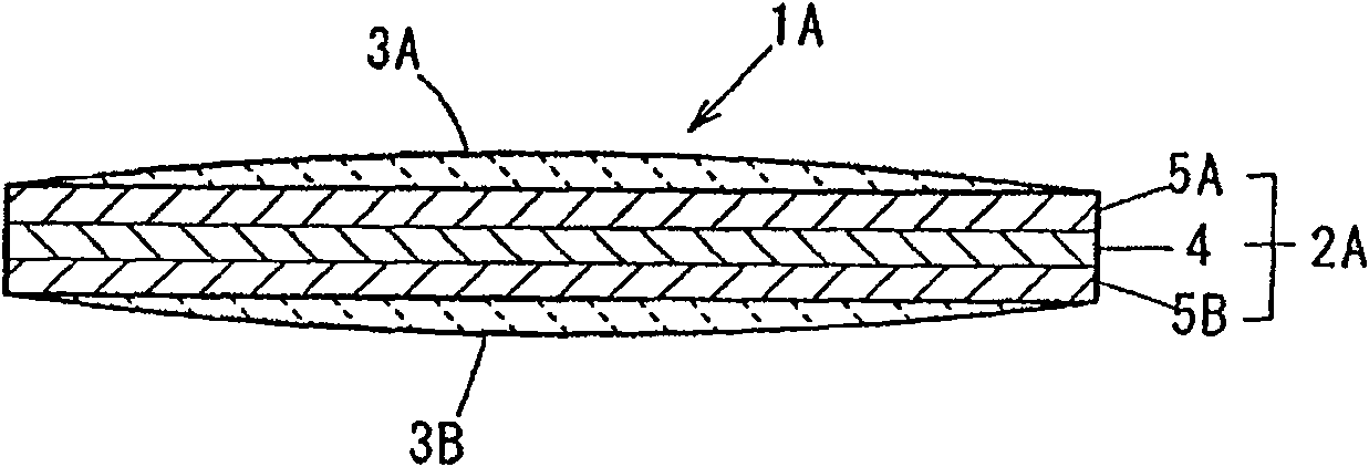
[0050] An aluminum plate (thickness: 0.5 mm) and a copper plate (thickness: 1.0 mm) made of oxygen-free copper were prepared to prepare a clad material with a final thickness of 200 μm. The above-mentioned cladding material is produced by superimposing the above-mentioned copper plate on both sides of the above-mentioned aluminum plate, crimping the superposed material at a reduction rate of 65-75%, and further finishing rolling the crimped material. The total reduction from superimposed material to cladding material is 92%. On the other hand, a copper plate (plate thickness: 2.5 mm) of oxygen-free copper was rolled to produce a Cu single-layer material (copper plate) with a thickness of 200 μm. Thereafter, these cladding materials and Cu single-layer materials were cut, respectively, to produce strip-shaped primary core materials with a width of 2 mm. The cladding material and the Cu single-layer material described above respectively constitute the core material raw material...


PUM

PropertyMeasurementUnit
thicknessaaaaaaaaaa
electrical resistivityaaaaaaaaaa

Abstract

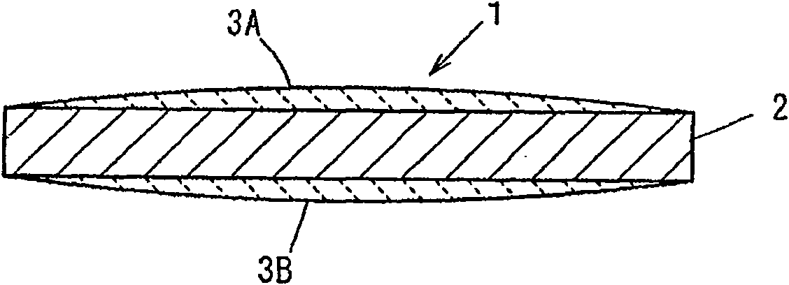
The present invention provides a method for producing electrode wires for solar cells, which can easily produce solar cells that are easily plastically deformed by thermal stress generated in a semiconductor substrate without providing a softening annealing step, and that can prevent damage caused by thermal stress Use electrode wire. The manufacturing method of the electrode wire of the present invention comprises: processing the core material raw material, the core material processing step of making strip-shaped core material (2); Hot-dip welding process of forming hot-dip welding layers (3A) and (3B) on the surface of material (2). In the hot-dip soldering process, the liquid temperature of the molten solder liquid is 250°C to 380°C, and the immersion time of the core material is 6 to 10 seconds when the liquid temperature is 250°C to less than 280°C. , 3 to 10 seconds when the liquid temperature is 280° C. to 350° C., or 3 to 5 seconds when the liquid temperature exceeds 350° C. but 380° C. or less.

Description

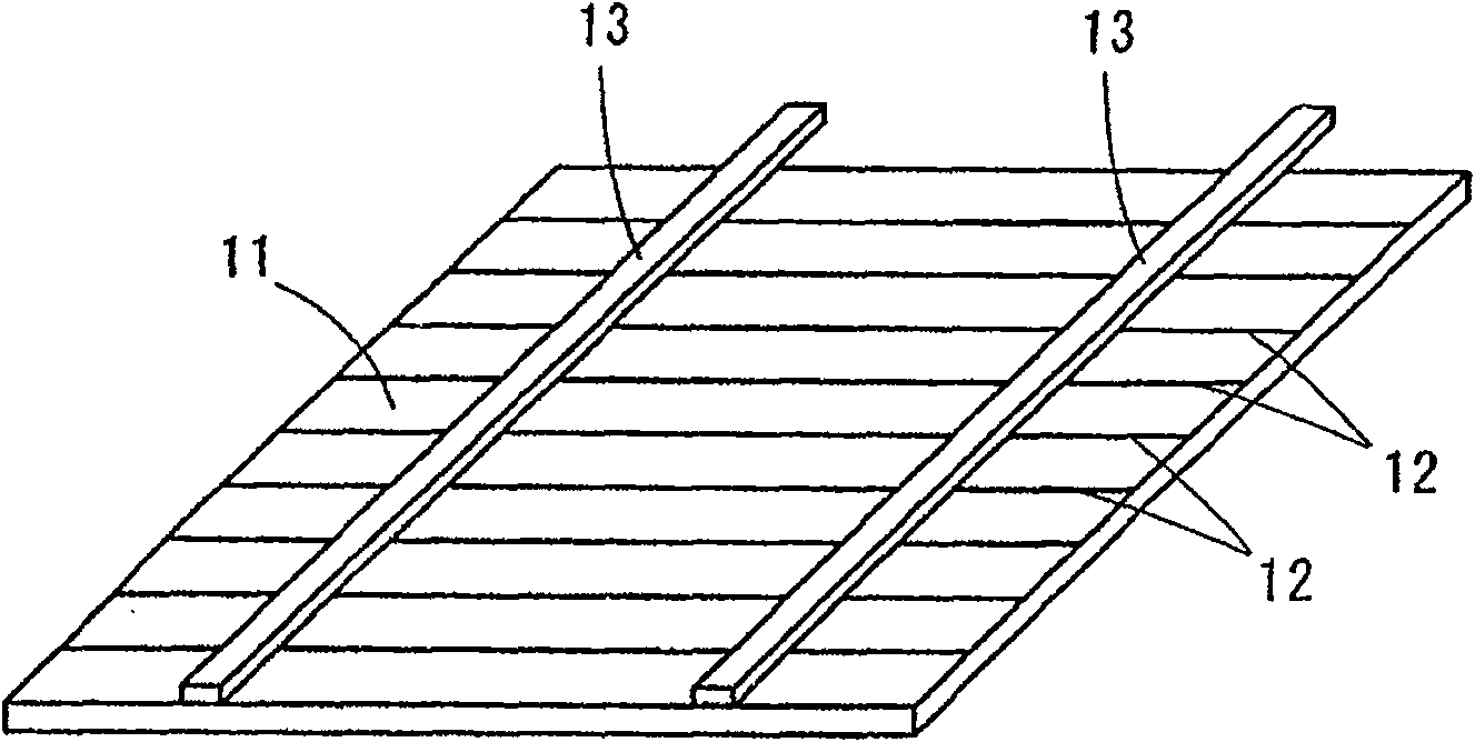
technical field [0001] This invention relates to the manufacturing method of the electrode wire material used as the lead wire for connection of a solar cell. Background technique [0002] Such as image 3 As shown, the solar cell includes a semiconductor substrate 11 formed of a silicon semiconductor having a PN junction, a plurality of linear surface electrodes 12 arranged in parallel with the surface of the semiconductor substrate 11, and a connecting wire connected to the plurality of surface electrodes 12. Lead 13. The connection leads 13 are soldered to solder strips formed to intersect the plurality of surface electrodes 12 . Usually, in order to obtain a desired electromotive force, a plurality of solar cells are connected in series and used. The series connection of solar cells is carried out in the following manner, one surface (lower surface) of the lead wire for connection is welded to the surface electrode of one solar cell, and the other surface (upper surfac...

Claims


Application Information

Patent Timeline
Patent Type & Authority Patents(China)
IPC IPC(8): H01L31/04
CPCH01L31/022425Y02E10/50H01L31/05
Inventor 盐见和弘冈田诚石尾雅昭
Owner HITACHI METALS LTD
Features
  • R&D
  • Intellectual Property
  • Life Sciences
  • Materials
  • Tech Scout
  • Unparalleled Data Quality
  • Higher Quality Content
  • 60% Fewer Hallucinations
Learn More