Permanent magnetism minisize robot

A technology of micro-robots and robots, applied in the field of robotics, can solve the problems of poor posture control and movement flexibility, and achieve the effects of flexible movements, convenient operation, and small size

Inactive Publication Date: 2009-10-28
INST OF ELECTRICAL ENG CHINESE ACAD OF SCI
View PDF10 Cites 0 Cited by
  • Summary
  • Abstract
  • Description
  • Claims
  • Application Information

AI Technical Summary

Problems solved by technology

[0005] The purpose of the present invention is to overcome the shortcomings of existing micro-robots such as poor posture control and movement flexibility, and to design a permanent magnet micro-robot that can be used for inspection and operation in tiny non-magnetic pipelines, especially biological pipelines.

Method used


Image

  • Permanent magnetism minisize robot
  • Permanent magnetism minisize robot

Examples


Embodiment Construction

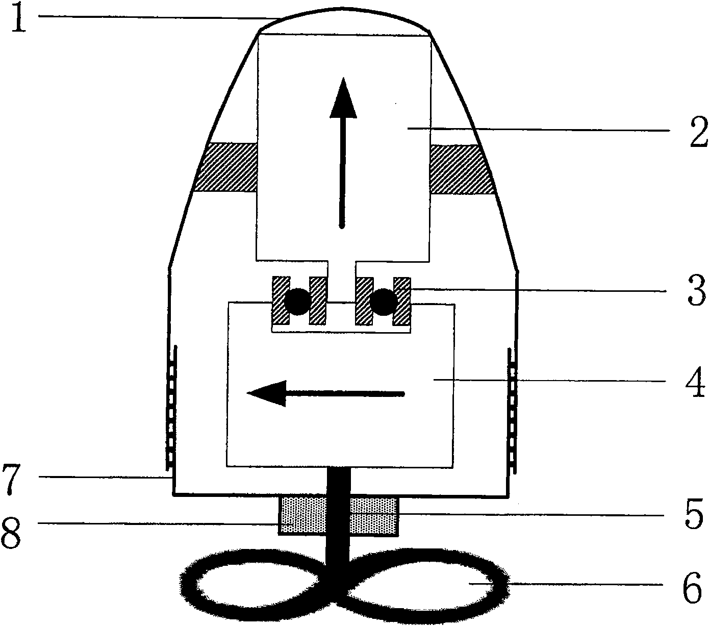
[0014] like figure 1 shown. The permanent magnet micro-robot of the present invention is composed of a shell 1, an axially magnetized permanent magnet block 2, a radially magnetized permanent magnet block 4, a non-magnetic miniature bearing 3 and a propeller 6. The head of the shell 1 is smooth, without protrusions and grooves in the middle. There is a spiral groove at the inner rear end of the fuselage shell 1, which is airtightly matched with the bottom 7 peripheral spiral grooves, so that it is convenient for the disassembly of the robot. The robot bottom 7 has a cavity 8, and an axial through hole is opened in the middle of the cavity 8. Filling the lubricating grease in the cavity 8 can prevent the liquid in the pipeline from entering the fuselage. The inner upper end of the shell 1 is made into two protrusions, and the axially magnetized permanent magnet block 2 is pasted on the two protrusions. The axially magnetized permanent magnet block 2 is connected with the ra...


PUM


Abstract

A permanent magnet miniature robot consists of a casing (5), an axially magnetized permanent magnet block (1), a radially magnetized permanent magnet block (2), a nonmagnetic miniature bearing (3) and a propeller (4). The head of the housing (5) is smooth, and the bottom (6) has a cavity (7), and the cavity is filled with grease. An axially magnetized permanent magnet block (1) and a radially magnetized permanent magnet block (2) are connected through a non-magnetic miniature bearing (3). The radially magnetized permanent magnet block (2) and the propeller (4) are fixedly connected through the shaft (8) of the propeller. The external magnetic field is generated by a rotating magnetic field device and a uniform magnetic field device. The rotating magnetic field device is composed of three sets of orthogonal Helmholtz coils, a sinusoidal current source and a phase shifter. The uniform magnetic field device is composed of three sets of orthogonal Helmholtz coils and three group of DC current sources. Under the action of the rotating magnetic field, the robot uses the radially magnetized permanent magnet block (2) to rotate and generate axial driving force for driving. At the same time, under the action of the deflection guidance of the uniform magnetic field, the robot realizes flexible steering and moves along the desired trajectory.

Description

technical field [0001] The invention relates to the technical field of robots, in particular to a micro robot. Background technique [0002] With the development of ultra-precision machining, micro-electro-mechanical integration and functional materials-based drive technology, micro-robots have become a research hotspot at home and abroad, especially wireless endoscopes that enter the human body, vascular robots, and small pipeline detection devices for industrial equipment. micro robots. Due to the special working environment, this type of micro-robot cannot be a simple miniaturization of ordinary robots, especially in the way of driving will be very different from ordinary robots. At present, the driving methods of micro-robots can be roughly divided into two categories: one is driven by the actuator of the robot body; The actuator realizes wireless drive through external field excitation. [0003] At present, the actuators of most micro-robots are still driven by body ...

Claims


Application Information

Patent Timeline
Patent Type & Authority Patents(China)
IPC IPC(8): F16L55/30F16L101/30
Inventor 宋涛杨岑玉王铮王喆于阳
Owner INST OF ELECTRICAL ENG CHINESE ACAD OF SCI
Why Eureka
Try Eureka