Heat pipe and radiating model group

A heat dissipation module and heat pipe technology, applied in indirect heat exchangers, lighting and heating equipment, cooling/ventilation/heating transformation, etc., can solve the problems of slowing down the circulation speed of working fluid and reducing the heat transfer performance of heat pipe 10, etc., to achieve Effect of improving heat transfer efficiency

Inactive Publication Date: 2009-10-28
HONG FU JIN PRECISION IND (SHENZHEN) CO LTD +1
View PDF4 Cites 0 Cited by
  • Summary
  • Abstract
  • Description
  • Claims
  • Application Information

AI Technical Summary

Problems solved by technology

Due to the existence of this shearing force, the circulation speed of the working fluid in the heat pipe 10 is greatly slowed down, which reduces the heat transfer performance of the heat pipe 10. For the long heat pipe with a smaller diameter of the shell 102, even the condensed liquid cannot Smoothly return to the evaporation section A for circulation heat dissipation

Method used


Image

  • Heat pipe and radiating model group
  • Heat pipe and radiating model group
  • Heat pipe and radiating model group

Examples


Embodiment Construction

[0015] A heat pipe and heat dissipation module will be further described in detail below with reference to the drawings and embodiments.

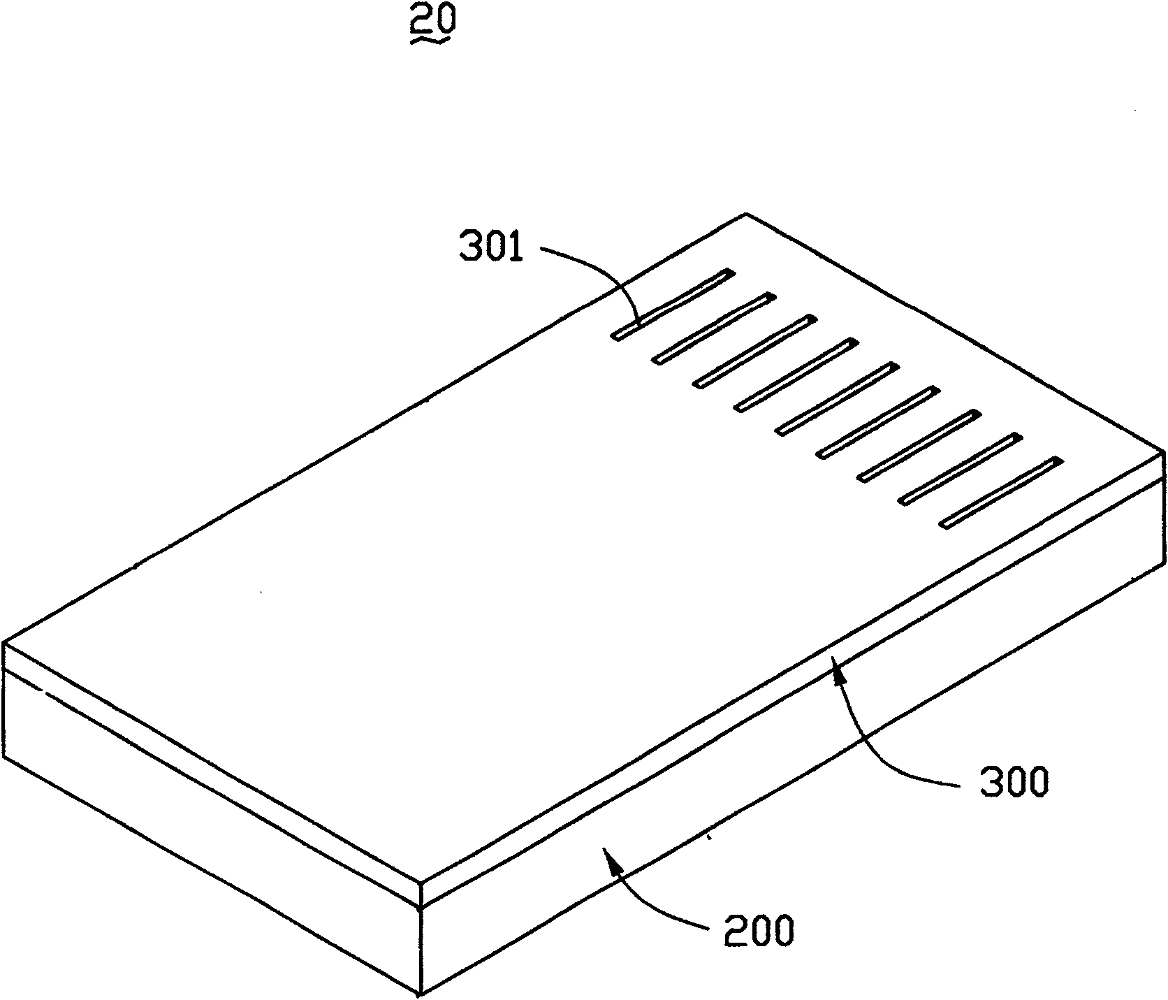
[0016] Such as image 3 and Figure 4 As shown, the heat pipe 20 of the first embodiment of the present invention includes a body 200, a cover 300 matched with it, and a working fluid 400 dispersed in the body 200. The shape of the body 200 can be rectangular, square or other regular. or irregular shape; the shape of the cover body 300 may be the same as that of the main body, or different, as long as the two cooperate to seal the working fluid; Low liquid substances, such as water, ethanol, acetone, etc., and nanoparticles such as nano-copper particles can be added to the working fluid 400 to improve its thermal conductivity.

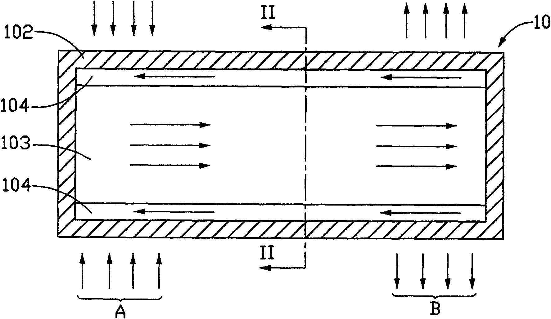
[0017] The body 200 includes an evaporation chamber 210, a condensation chamber 220, an evaporation channel 230 and a return channel 240, the evaporation chamber 210 includes a steam output side 212 and a liquid i...


PUM


Abstract

The invention relates to a heat pipe, which includes a cover body and a body, the body includes an evaporation chamber, a condensation chamber, an evaporation channel and a return flow channel, a plurality of partitions are arranged in the condensation chamber, at least one partition It has a cavity that communicates with the outside world. The evaporation cavity has a steam output side and a liquid input side. The condensation cavity has a steam input side and a liquid output side. The evaporation channel is arranged between the steam output side and the steam input side. Between the evaporation chamber and the condensation chamber, the return passage is set between the liquid output side and the liquid input side and communicates the condensation chamber with the evaporation chamber, and a working fluid is filled in the evaporation chamber, the condensation chamber, the return passage and the evaporation passage. in the channel formed. In addition, the invention also provides a cooling module with the heat pipe. The heat pipe can effectively solve the heat dissipation problem of the notebook computer which is developing towards light, thin, short and small.

Description

【Technical field】 [0001] The invention relates to a heat pipe and a cooling module with the heat pipe. 【Background technique】 [0002] A heat pipe is a heat transfer device that holds a proper amount of working fluid in a sealed, low-pressure metal shell with good thermal conductivity. Its working principle is: use the working fluid to convert vapor and liquid in the shell to absorb or release heat. The working fluid is usually a liquid substance with high heat of vaporization, good fluidity, stable chemical properties, and low boiling point, such as water, ethanol, acetone, etc. The heat pipe has an evaporating end and a condensing end. When the evaporating end is in contact with the heat source to absorb heat, the working fluid inside is heated and evaporated and absorbs a large amount of heat of vaporization. The formed gas quickly diffuses to the condensing end to cool and release heat, and then forms again after cooling. The liquid flows back along the inner wall of th...

Claims


Application Information

Patent Timeline
Patent Type & Authority Patents(China)
IPC IPC(8): F28D15/02H05K7/20G06F1/20
CPCF28D15/0233H01L23/427H01L2924/0002F28D15/04Y10T29/49353F28D15/046H01L2924/00
Inventor 张仁淙
Owner HONG FU JIN PRECISION IND (SHENZHEN) CO LTD
Why Eureka
Try Eureka