
Energy source self-help river water contamination treating apparatus

A self-service, water pollution technology, applied in the fields of energy wastewater treatment, biological water/sewage treatment, water/sludge/sewage treatment, etc., to achieve the effect of enhancing treatment efficiency, saving operating and management costs, and improving aeration efficiency

Inactive Publication Date: 2009-11-11
SOUTH CHINA UNIV OF TECH
View PDF5 Cites 2 Cited by
  • Summary
  • Abstract
  • Description
  • Claims
  • Application Information

AI Technical Summary

Problems solved by technology

[0003] The purpose of the present invention is to aim at the shortcomings of existing river water pollution control devices, and provide a kind of energy self-service river water pollution control device with multi-technology integration, low management cost, energy self-help and flexible movement

Method used


Image

  • Energy source self-help river water contamination treating apparatus
  • Energy source self-help river water contamination treating apparatus
  • Energy source self-help river water contamination treating apparatus

Examples


Embodiment 1

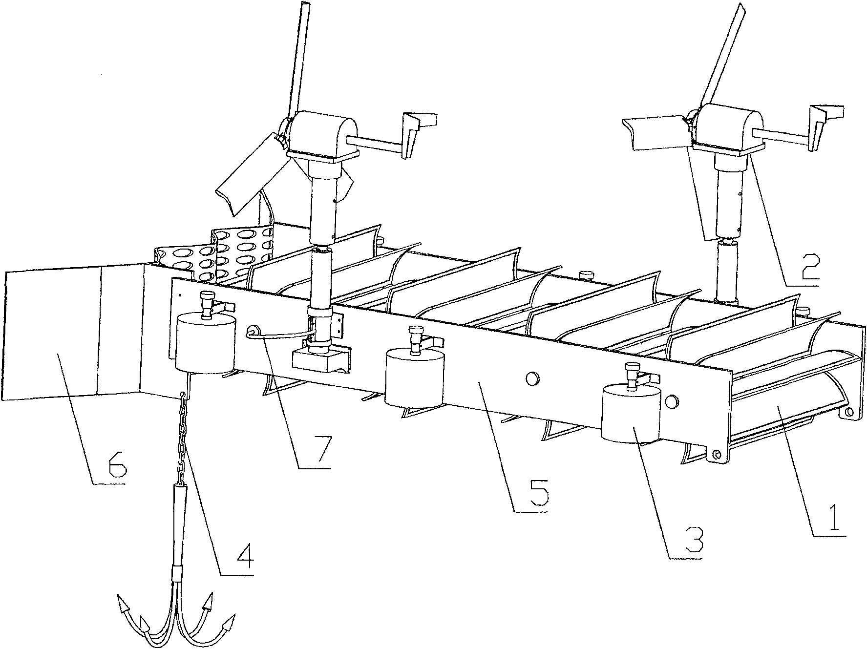
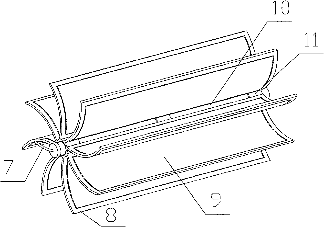
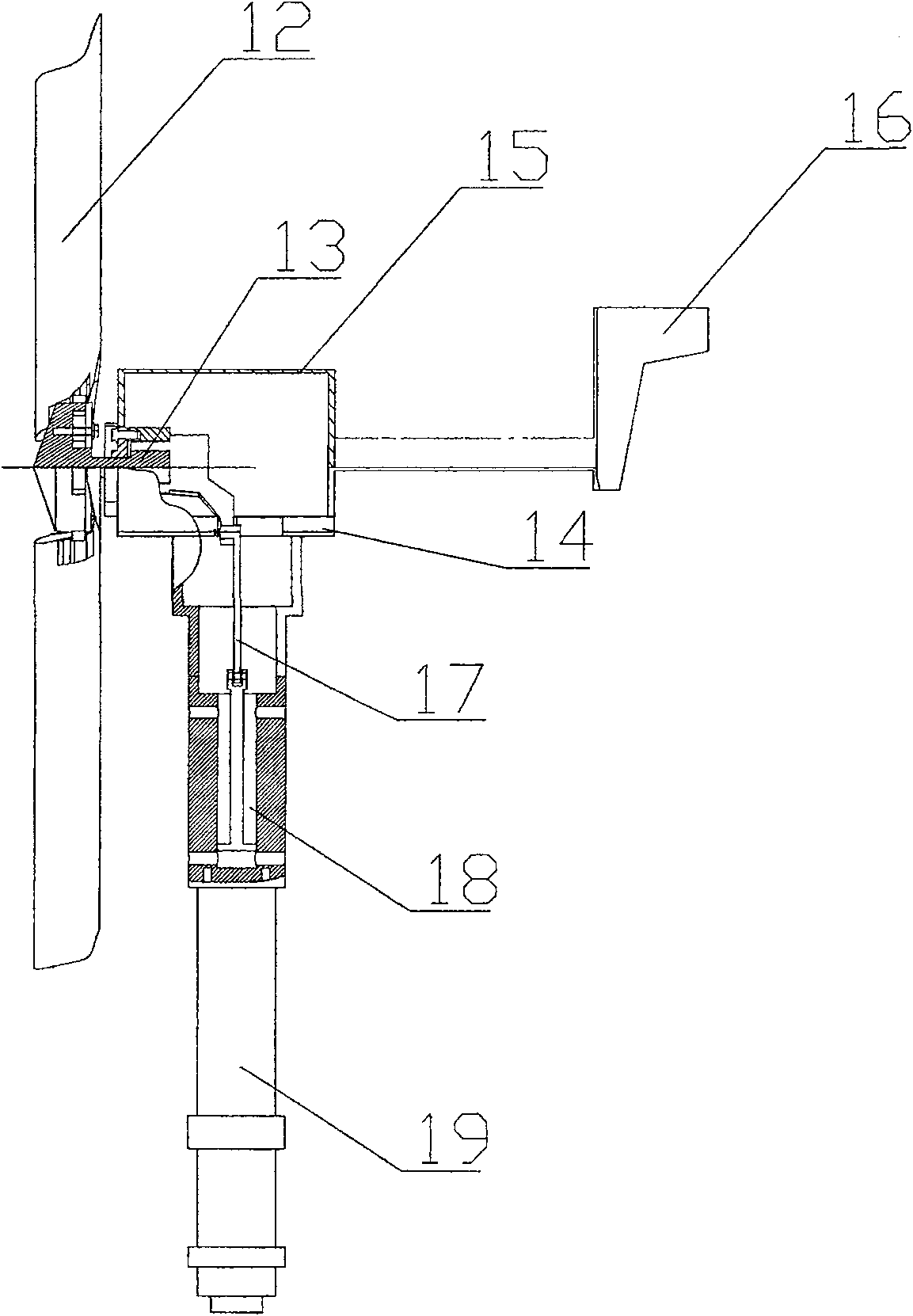
[0030] Such as figure 1 As shown, the energy self-service river water pollution control device of the eight-carrier fixed frame vertical suspension mechanism is mainly composed of such figure 2 The shown impeller biofilm reactor 1, such as image 3 Shown wind energy aeration mechanism 2, such as Figure 5 Shown suspension mechanism 3, as Image 6 Shown parking mechanism 4, frame 5, such as Figure 7 The slag retaining plate 6 shown is integrated; where: as figure 2 The shown impeller biofilm reactor 1 is mainly composed of connecting pipe 7, carrier fixing frame 8, biofilm carrier 9, central aeration shaft 10 and ring 11. The carrier fixing frame 8 is evenly distributed and fixed on three coaxial On the three rings 11, the biofilm carrier 9 is fixed on the carrier fixing frame 8, and the central aeration shaft 10 with aeration micropores on the peripheral wall passes through the three rings 11 and is flexibly connected in the shape of an impeller; image 3 Shown wind en...

Embodiment 2

[0039] Such as Figure 8 Shown is the energy self-service river water pollution control device of the twelve-carrier fixed frame horizontal suspension device, except Figure 9 The impeller biofilm reactor 1 shown with Figure 10 Except for the suspension mechanism 3 shown, other components and their connections are the same as those in Embodiment 1.

[0040] Such as Figure 9 In the twelve carrier fixed frame impeller biofilm reactor shown, the biofilm carrier 9 is fixed on the carrier fixed frame 8, and the carrier fixed frame 8 is planar. Twelve carrier fixing frames 8 are evenly distributed and fixedly installed on three coaxial rings, which are in the shape of impellers.

[0041] Such as Figure 10 As shown, the suspension mechanism 3 is composed of a tank body 23 and a connecting frame 24. The tank body 23 is a hollow thin-walled container with a horizontal structure. There are four suspension mechanisms 3 arranged symmetrically and evenly on the sides of the frame 5....


PUM


Abstract

The invention relates to a river water pollution control device, more specifically an energy self-service river water pollution control device. The device is mainly composed of an impeller type biofilm reactor (1), a wind energy aeration mechanism (2), a suspension mechanism (3), a parking mechanism (4), a frame (5) and a slag retaining plate (6); Their connections are as follows: the impeller biofilm reactor (1) is movably connected between the two side plates of the frame (5), the wind energy aeration mechanism (2) is movably installed above the side plates of the frame (5), and the suspension mechanism ( 3) It is fixedly installed on both sides of the frame (5), the parking mechanism (4) is fixedly installed under one end of the side plate of the frame (5), and the slag retaining plate (6) is fixedly installed on the upstream end of the frame (5). The device has the characteristics of technology integration, can greatly save operating costs and management costs, self-help energy and high sewage treatment efficiency, flexibility and convenience.

Description

technical field [0001] The invention relates to a river water pollution control device, more specifically an energy self-service river water pollution control device. Background technique [0002] The problem of river water pollution has always been a common concern of all countries in the world. The pollution of river water in our country is becoming more and more serious and urgently needs to be treated. At present, water pollution control equipment at home and abroad is mainly developed for complete sets of equipment in sewage treatment plants, while there are few equipment systems for the treatment of polluted rivers and lakes. For river (lake) water pollution control equipment, it mainly focuses on aeration boats, suspension chain aeration devices, fixed aeration equipment on the shore, and bioreactors. Aeration boats have a single treatment method, limited effect, high cost, The disadvantages of complex operation and difficult management, while the suspension chain ae...

Claims


Application Information

Patent Timeline
Patent Type & Authority Patents(China)
IPC IPC(8): C02F3/10C02F3/12C02F3/18C02F7/00
CPCY02W10/10Y02W10/33
Inventor 陈维平江帆李元元朱权利
Owner SOUTH CHINA UNIV OF TECH
Learn More