
High precision angle-measuring method

A high-precision, angle measurement technology, applied in the field of angle measurement, can solve the problems that the angle measurement accuracy cannot meet the requirements of use, cannot meet the requirements of large load measurement, and the angle measurement range is small, so as to achieve large load measurement, the method is simple, The effect of high test accuracy

Active Publication Date: 2009-11-11
BEIJING RES INST OF SPATIAL MECHANICAL & ELECTRICAL TECH
View PDF4 Cites 0 Cited by
  • Summary
  • Abstract
  • Description
  • Claims
  • Application Information

AI Technical Summary

Problems solved by technology

The angle measuring device using this method can generally have a load capacity of 1500kg or more, but its angle measuring accuracy is generally below 1″
For high-precision assembly and testing, the angle measurement accuracy of 1″ can no longer meet the current use requirements. For example, the geometric accuracy calibration of remote sensors requires the angle measurement accuracy to reach 0.4″ or even higher.
At present, the measurement method that can realize the angle measurement accuracy below 0.5 ", such as Cai Shuzhang, Jing Fangsheng, "Photoelectric Autocollimator and Its Application" and "Multi-tooth Indexing Table" published by China Metrology Press in 1986 The measurement method introduced has a small angle measurement range (generally below classification) or a load capacity of less than 100 kg, which cannot meet the requirements of large load and wide range angle measurement.

Method used


Image

  • High precision angle-measuring method
  • High precision angle-measuring method
  • High precision angle-measuring method

Examples


Embodiment Construction

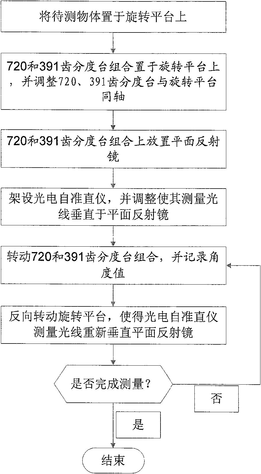
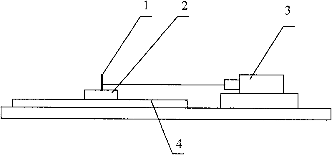
[0024] Such as figure 1 Shown is the flowchart block diagram of angle measuring method of the present invention, figure 2 It is a structural diagram of the angle measuring device used in the method of the present invention, wherein 1 is a plane mirror, 2 is a combination of a 720-tooth indexing table and a 391-tooth indexing table, 3 is a photoelectric autocollimator, and 4 is a rotating platform. The rotating platform provides rotation and bearing functions, and the angle measurement function is realized by the combination of 720-tooth indexing table and 391-tooth indexing table and photoelectric autocollimator. Place the object to be measured on the rotating platform, and its position can be selected arbitrarily. Put the combination of the 720-tooth indexing table and the 391-tooth indexing table on the rotating platform, and place it on the combination of the 720-tooth indexing table and the 391-tooth indexing table. Place the plane reflector so that the horizontal rotati...


PUM


Abstract

A high-precision angle measurement method. First, the object to be measured is placed on the rotating platform, and then the 720-tooth indexing table and the 391-tooth indexing table are combined on the rotating platform, and the 720-tooth indexing table and the 391-tooth indexing table are combined Place the plane mirror on the indexing table combination; then adjust the photoelectric autocollimator so that the measuring light emitted by it is aimed at the plane mirror; turn the combination of the 720-tooth indexing table and the 391-tooth indexing table to rotate an angle, and Record the value of the rotation angle at this time, and then reversely rotate the rotary platform so that the measurement light emitted by the photoelectric autocollimator is re-aimed at the same aiming position on the plane mirror. At this time, the 720-tooth indexing table and the 391-tooth indexing table are combined The value of the rotation angle is the angle value of the rotation of the sensitive device to be tested. The method of the invention has simple operation steps and can realize high-precision testing of the whole circle angle.

Description

technical field [0001] The invention relates to an angle measurement method, in particular to a large-scale and high-precision angle measurement method used for assembly and testing of aerospace remote sensors. Background technique [0002] During the installation and adjustment process of aerospace remote sensors, angle tests with a large measurement range are often required, such as system integration tests and internal orientation element tests. Angle test with high precision and large measurement range is one of the indispensable means in the development process of remote sensing cameras. It plays an important role in the process of optical inspection and assembly. Camera) and angle test camera system detection and other links, the angle measurement accuracy directly affects the quality of the camera. With the increasing requirements for the resolution of remote sensors, aerospace remote sensors are developing in the direction of telephoto, which will inevitably make th...

Claims


Application Information

Patent Timeline
Patent Type & Authority Patents(China)
IPC IPC(8): G01B11/26
Inventor 张继友伏瑞敏何品将党一涵
Owner BEIJING RES INST OF SPATIAL MECHANICAL & ELECTRICAL TECH
Learn More