Linear vibration and overload combinatorial testing method and apparatus thereof
A combination test and linear vibration technology, applied in the field of measurement, can solve the problems of product influence difference, not, not in compliance with combination test, etc.
- Summary
- Abstract
- Description
- Claims
- Application Information
AI Technical Summary
Problems solved by technology
Method used
Image
Examples
Embodiment 1
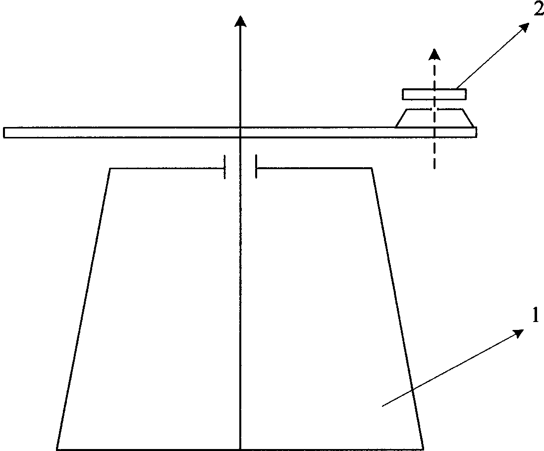
[0017] Example 1: Combining figure 1 , a combined linear vibration and overload testing device of the present invention, which is composed of a disc centrifuge and a high-speed rotating platform, the high-speed rotating platform is installed on the disc centrifuge, the rotating shaft of the disc centrifuge and the high-speed rotating platform The shafts of the rotors are parallel, and the speed of the disc centrifuge and the speed of the high-speed rotating platform can be adjusted.
[0018] A kind of linear vibration and overload combined testing method of the present invention, the steps are as follows:
[0019] Step 1: Install the measured inertial instrument on the high-speed rotating platform, and the test signal is transmitted to the ground monitoring computer through the slip ring;
[0020] Step 2: Power up the disc centrifuge and high-speed rotating platform;
[0021] Step 3: Calibrate the input shaft of the inertial instrument under test;
[0022] Step 4: Start the...
Embodiment 2
[0024] Example 2: Combining figure 1 , the combined testing method of line vibration and overload of the present invention, the steps are as follows:
[0025] (1) Install the inertial instrument under test on the high-speed rotating platform, align the input axis of the inertial instrument under test with the zero position of the high-speed rotating platform (allowable error of 10 arc seconds), and connect the table with a test signal cable during installation The slip ring on the ground and the output signal socket of the measured inertial instrument, and then another signal cable is used to connect the signal seat of the centrifuge base and the acquisition card of the ground monitoring computer, so that the signal of the inertial instrument is transmitted to the ground monitoring computer through the slip ring;
[0026] (2) Power up the disc centrifuge and high-speed rotating platform, and control them to zero;
[0027] (3) After installing the input shaft of the inertial i...
Embodiment 3
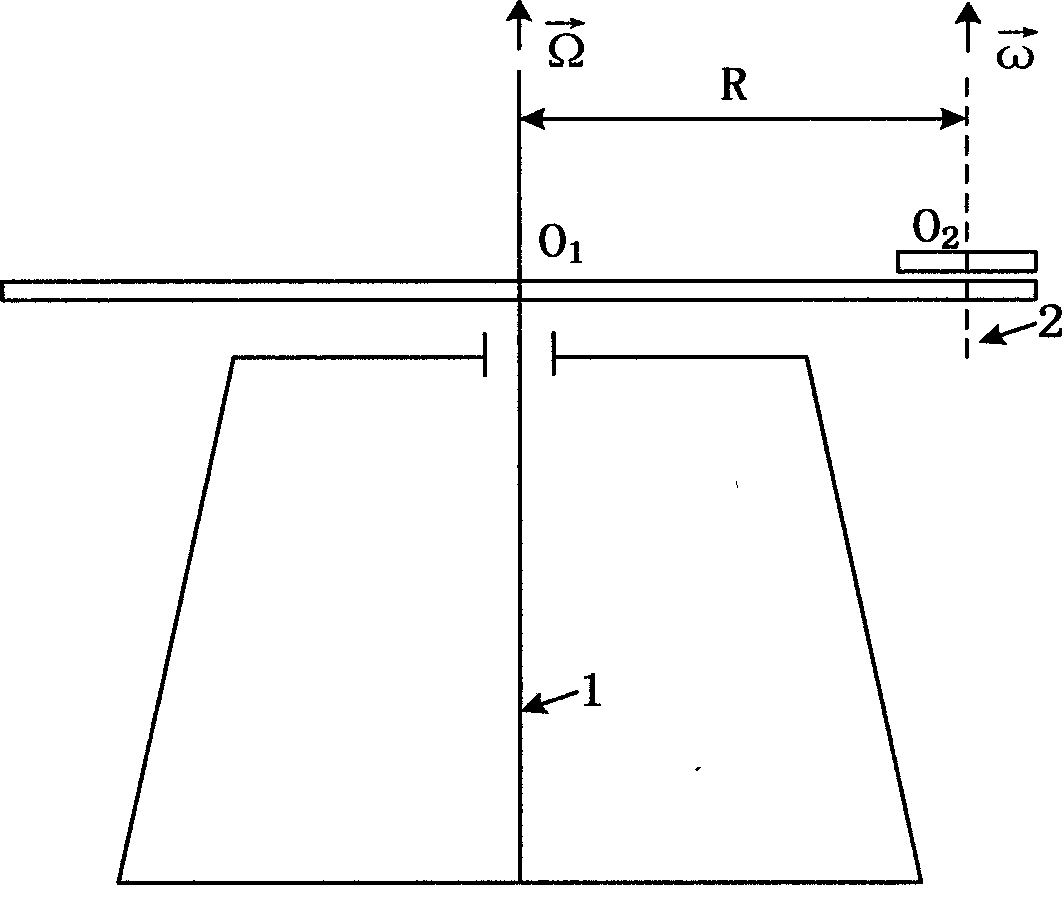
[0030] Example 3: Binding figure 1 , figure 2 , the invention works like this:
[0031] figure 2 Among them, "1" is the rotating shaft of the disc centrifuge, "2" is the rotating shaft of the high-speed rotating platform, the "1" axis is parallel to the "2" axis and the distance between the axes is R, is the rotational angular velocity vector of the rotary spindle of the disc centrifuge, is the rotation angular velocity vector of the rotary axis of the high-speed rotating platform, and it is stipulated that and The positive direction of is vertically upward. Because O 2 A point is always a point on the disk of a disc centrifuge, so O 2 Point without Coriolis acceleration and relative acceleration, can be obtained O 2 The absolute acceleration of the point relative to the fixed coordinate system of the ground base is Its magnitude is RΩ 2 , whose direction is O 2 The point points along the centrifuge disc to the center of rotation of the centrifuge. Since the...
PUM
 Abstract
Description
Claims
Application Information
 - R&D
- Intellectual Property
- Life Sciences
- Materials
- Tech Scout
- Unparalleled Data Quality
- Higher Quality Content
- 60% Fewer Hallucinations
Browse by: Latest US Patents, China's latest patents, Technical Efficacy Thesaurus, Application Domain, Technology Topic, Popular Technical Reports.
© 2025 PatSnap. All rights reserved.Legal|Privacy policy|Modern Slavery Act Transparency Statement|Sitemap|About US| Contact US: help@patsnap.com


