Azimuth element and distortion calibration method in interferometric imaging spectrometer

A technology of imaging spectrometer and internal azimuth elements, which is applied in the field of optical precision measurement, and can solve the problems of low calibration accuracy

Active Publication Date: 2021-09-14
XI'AN INST OF OPTICS & FINE MECHANICS - CHINESE ACAD OF SCI
View PDF0 Cites 0 Cited by
  • Summary
  • Abstract
  • Description
  • Claims
  • Application Information

AI Technical Summary

Problems solved by technology

[0004] In order to solve the problem of low calibration accuracy existing in the traditional collimator plus two-dimensional turntable camera internal orientation element and distortion calibration device, the present invention proposes an interferometric imaging spectrometer internal orientation element and distortion calibration method

Method used


Image

  • Azimuth element and distortion calibration method in interferometric imaging spectrometer
  • Azimuth element and distortion calibration method in interferometric imaging spectrometer
  • Azimuth element and distortion calibration method in interferometric imaging spectrometer

Examples


Embodiment Construction

[0042] The present invention will be further described below in conjunction with accompanying drawing.

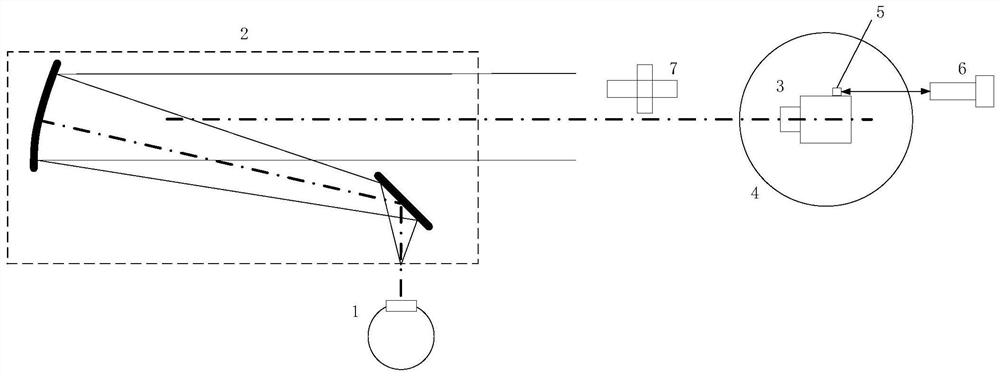
[0043] Such as figure 1 As shown, the azimuth element and distortion calibration device in the interferometric imaging spectrometer provided by the present invention includes an integrating sphere light source 1, a collimator 2, a two-dimensional turntable 4, a high-precision cube mirror 5, a high-precision angle measuring device 6 and an automatic Collimated theodolite7.

[0044] The integrating sphere light source 1 is located behind the focal plane of the collimator 2 and is used to uniformly illuminate the reticle target at the focal plane of the collimator 2 .

[0045] Collimator 2 is used to simulate an infinite target;

[0046] The two-dimensional turntable 4 is located directly in front of the light outlet of the collimator 2, and the table height of the two-dimensional turntable 4 is lower than the height of the bottom of the light outlet of the collimator 2; Be...


PUM


Abstract

In order to solve the problem of low calibration accuracy existing in the traditional collimator plus two-dimensional turntable camera internal azimuth element and distortion calibration device, the present invention proposes an interferometric imaging spectrometer internal azimuth element and distortion calibration method. The device includes an integrating sphere light source, a collimator, a two-dimensional turntable, a high-precision cube mirror, a high-precision angle measuring device, and an autocollimation theodolite; the high-precision cube mirror is set on the measured interference imaging spectrometer, and one of its mirrors is The optical axis of the interferometric imaging spectrometer is vertical; the high-precision angle measuring device is arranged behind the two-dimensional turntable, and forms a self-collimating optical path with the high-precision cubic mirror, which is used to measure the field angle of the measured interferometric imaging spectrometer; The collimating theodolite is set between the collimator and the two-dimensional turntable. The autocollimating theodolite can observe the crosshair target at the focal plane of the collimating light tube, and at the same time observe the self-collimating object reflected by the high-precision cube mirror. Straight image.

Description

technical field [0001] The invention belongs to the technical field of optical precision measurement, and relates to a calibration device for azimuth elements and distortions in an interferometric imaging spectrometer, which is suitable for high-precision measurement of the internal parameters of a camera with a small field of view, and is especially suitable for azimuth elements and distortions in an interferometric imaging spectrometer Measurement. Background technique [0002] With the development of aerospace technology, the geometric accuracy of the image information acquired by space cameras is becoming higher and higher. The calibration of internal orientation elements and distortion has become an important task and has been extensively studied in recent years. Some universities and research institutes at home and abroad have carried out more research on the calibration of internal orientation elements and distortion, focusing on the target position extraction algorit...

Claims


Application Information

Patent Timeline
Patent Type & Authority Patents(China)
IPC IPC(8): G01M11/02G01J3/02
CPCG01J3/0297G01M11/0264G01M11/0271
Inventor 刘尚阔周艳赵建科曹昆李晶田留德李坤薛勋
Owner XI'AN INST OF OPTICS & FINE MECHANICS - CHINESE ACAD OF SCI
Why Eureka
Try Eureka