
A dynamic measurement system and method for blade tip clearance based on microwave phase difference ranging

A technology of blade tip clearance and dynamic measurement, which is applied in the direction of measuring devices, using wave/particle radiation, instruments, etc., to achieve the effect of high-precision extraction

Active Publication Date: 2022-04-29
善测(天津)科技有限公司
View PDF0 Cites 0 Cited by
  • Summary
  • Abstract
  • Description
  • Claims
  • Application Information

AI Technical Summary

Problems solved by technology

[0005] The purpose of the present invention is to solve the deficiencies of the existing microwave blade tip clearance measurement method, and design a dynamic measurement system and method of blade tip clearance based on microwave phase difference ranging to achieve the following purposes:

Method used


Image

  • A dynamic measurement system and method for blade tip clearance based on microwave phase difference ranging
  • A dynamic measurement system and method for blade tip clearance based on microwave phase difference ranging
  • A dynamic measurement system and method for blade tip clearance based on microwave phase difference ranging

Examples


Embodiment Construction

[0036] The present invention will be described in further detail below in conjunction with the accompanying drawings and specific embodiments. It should be understood that the specific embodiments described here are only used to explain the present invention, not to limit the present invention.

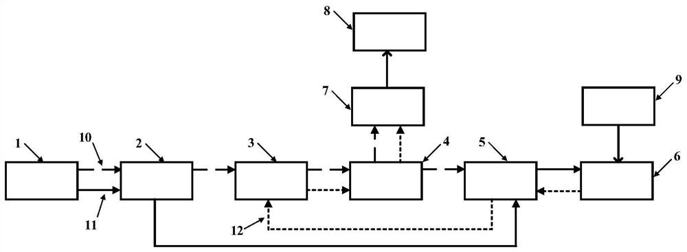
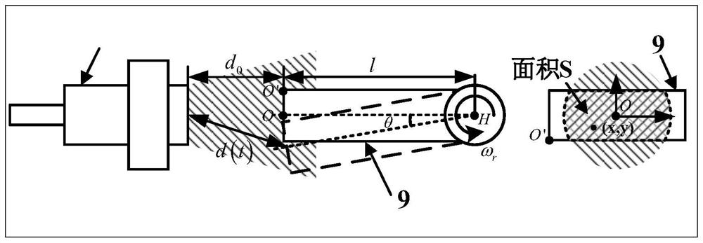
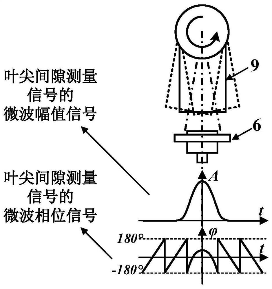
[0037] See figure 1 The present invention provides a tip clearance dynamic measurement system based on microwave phase difference ranging, including a microwave signal generation module 1, a signal power amplification module 2, a signal receiving and mixing module 3, a signal conditioning module 4, a circulator 5, and a microwave sensor 6. Signal acquisition module 7 and computer 8, wherein microwave signal generation module 1 provides radio frequency reference signal 10 and emission signal 11 with the same frequency; blade 9 to be measured reflects emission signal 11 to form reflection signal 12; signal power amplification module 2 uses It is used to amplify the power of the referen...


PUM


Abstract

The invention discloses a blade tip clearance dynamic measurement system and method based on microwave phase difference ranging. The measurement system includes a microwave signal generation module, a signal power amplification module, a signal receiving and mixing module, a signal conditioning module, a circulator, and a microwave sensor. , a signal acquisition module, and a computer, wherein the microwave signal generation module provides radio frequency stable transmission signals and reference signals, and the blades to be tested reflect the transmission signals to form reflected signals; the three ports of the circulator are respectively connected to the signal power amplification module, The microwave sensor is connected to the signal receiving and mixing module, the signal power amplification module is connected to the microwave signal generating module and the signal receiving and mixing module through connecting lines, the signal conditioning module is connected to the signal receiving and mixing module through connecting lines, and the signal acquisition The module is connected with the signal conditioning module through the connection line, and the computer is connected with the signal acquisition module through the connection line.

Description

technical field [0001] The invention relates to the field of non-contact distance dynamic measurement, in particular to a blade tip clearance dynamic measurement system and method based on microwave phase difference distance measurement. Background technique [0002] As the core working components of large rotating machines such as aero-engines and gas turbines, moving blades directly determine the performance of major equipment such as aircraft and ships. Among them, the tip clearance parameter between the tip of the moving blade and the inner wall of the casing is the key to affect the working efficiency and safety of the engine. The tip clearance of aero-engine turbine blades is usually designed within 3mm, and for every 0.0254mm reduction in the tip clearance, the fuel consumption rate will decrease by 0.1%, and the exhaust gas temperature will drop by 1°C; however, too small tip clearance will increase the blade The probability of collision and friction with the casing...

Claims


Application Information

Patent Timeline
Patent Type & Authority Patents(China)
IPC IPC(8): G01B15/00
CPCG01B15/00
Inventor 段发阶周琦牛广越刘志博李芳怡蒋佳佳傅骁
Owner 善测(天津)科技有限公司
Learn More