

Rain gauge
A rain gauge and rain collector technology, applied in the rain gauge field, can solve the problems of high price and complicated structure
- Summary
- Abstract
- Description
- Claims
- Application Information
AI Technical Summary
Problems solved by technology
Method used
Image

Examples
Embodiment Construction
[0020] Below in conjunction with accompanying drawing and embodiment, the present invention is described in further detail:
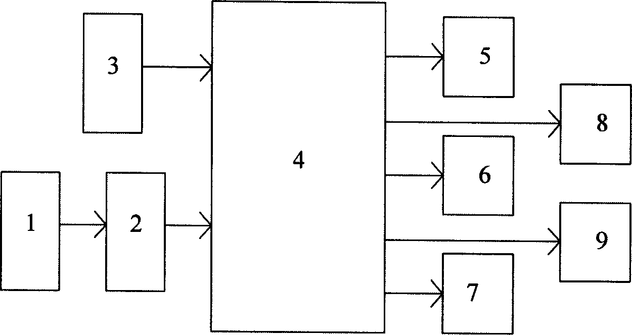
[0021] see figure 1 , the present invention includes a planar capacitive liquid level sensor and its signal conditioning circuit 1, A / D conversion circuit 2, microprocessor 4, watchdog circuit 3, liquid crystal display circuit 5, communication circuit 6, control interface circuit 7, real-time clock / Calendar circuit 8 and electric regulating valve control circuit 9 are composed.
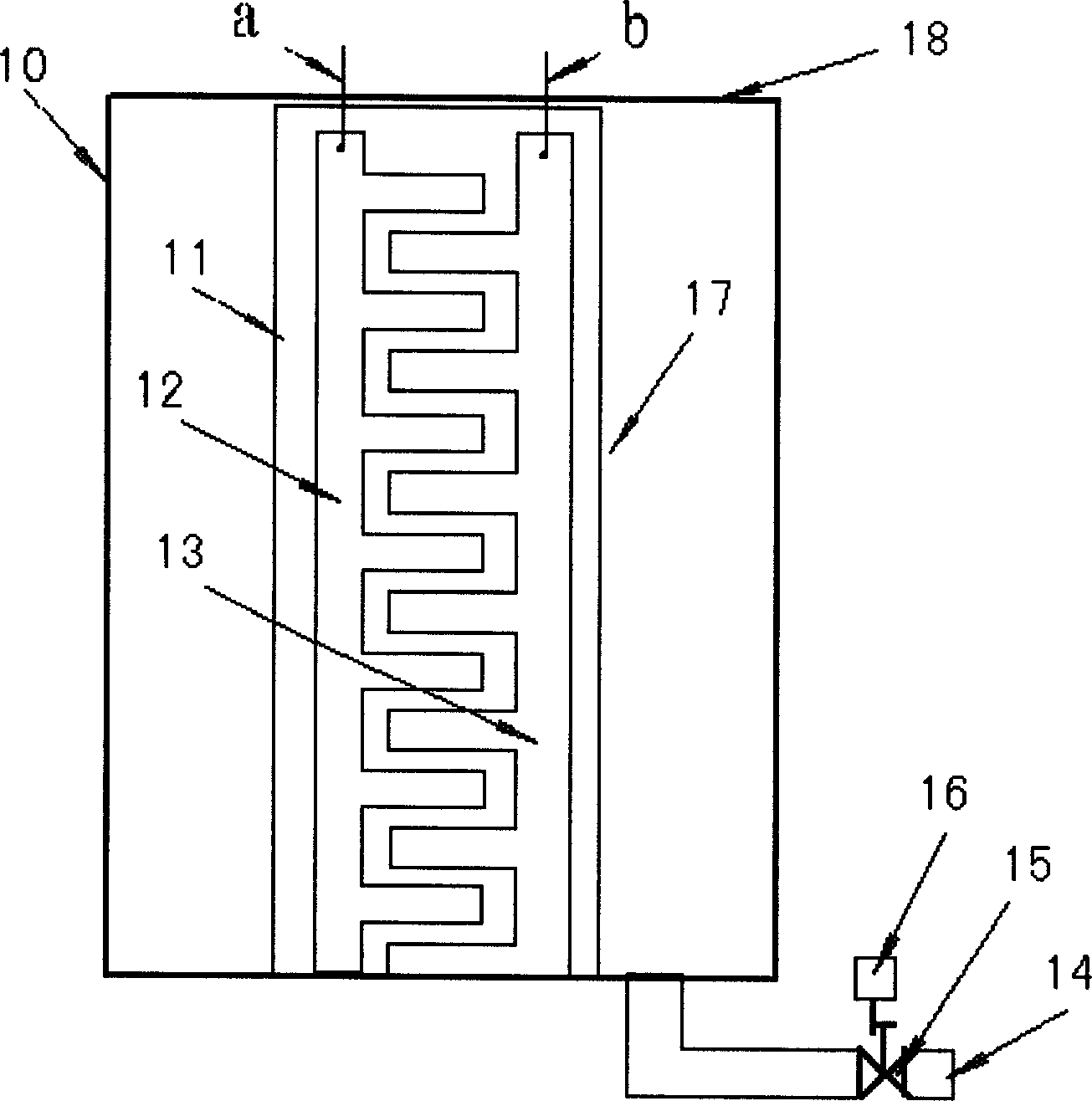
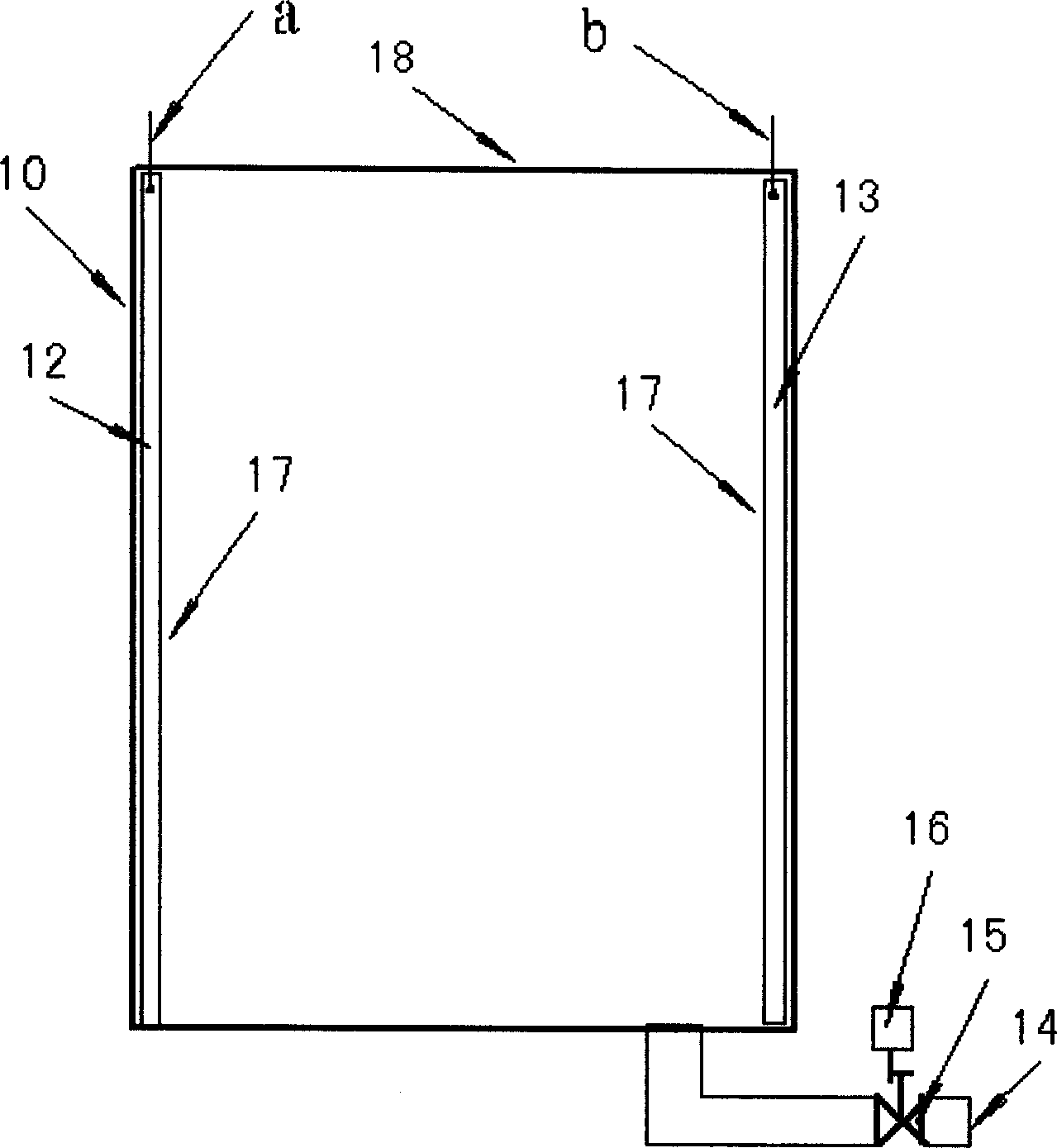
[0022] Such as figure 2 , image 3 As shown, the capacitive liquid level sensor 17 of the present invention is fixed inside the rain collector 10, the rain collector 10 is made of insulating material, the rainwater enters from the water inlet 18 of the rain collector 10, and the outlet pipe 14 of the rain collector 10 is provided with There is an electric control valve 15 with adjustable opening, and the rainwater inside the rain collector 10 can be discharged through the ...
PUM
 Abstract
Description
Claims
Application Information