Supercharge Your Innovation With Domain-Expert AI Agents!

TIG welding method

A welding method, a technology for joining surfaces, applied in the field of arc welding, which can solve the problems of high skill, complexity of the joining area, and non-constant welding thickness and quality

Active Publication Date: 2009-12-02
SN DETUDE & DE CONSTR DE MOTEURS DAVIATION S N E C M A
View PDF6 Cites 0 Cited by
  • Summary
  • Abstract
  • Description
  • Claims
  • Application Information

AI Technical Summary

Problems solved by technology

[0005] The disadvantage of this manual method is that it requires a high level of skill on the part of the operator due to the complexity of the connection area
Also, as the weld progresses, he has to keep adjusting the amount of energy produced because the thickness and mass of weld being welded is not constant

Method used


Image

  • TIG welding method
  • TIG welding method
  • TIG welding method

Examples


Embodiment Construction

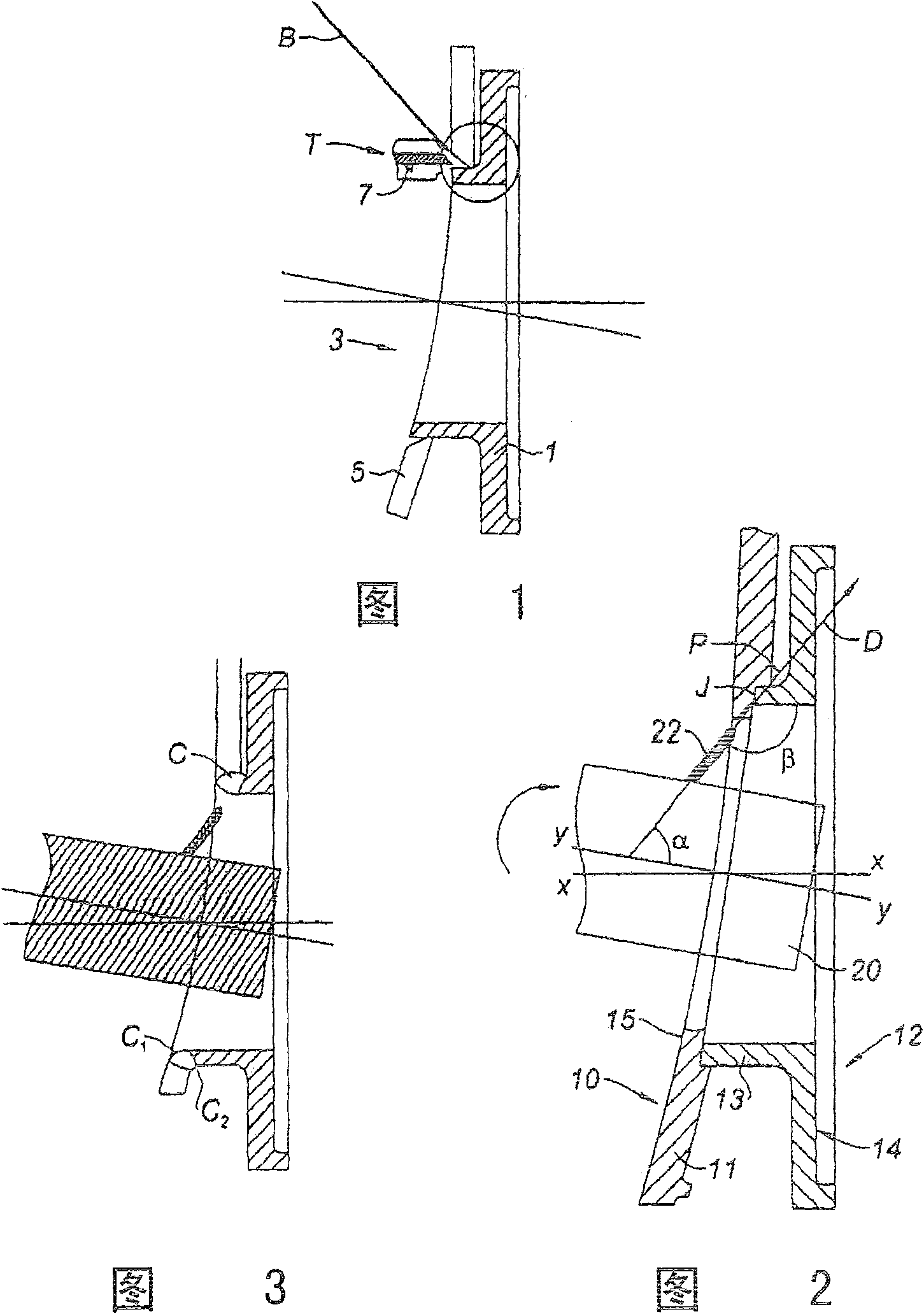
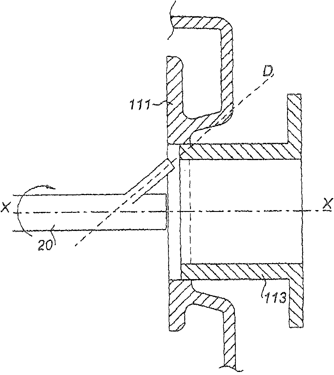
[0022] figure 2 Denotes a part of the casing 11 of the turbojet combustion chamber 10, which is at the level of the spark plug hole channel. The spark plug is shown without the remaining housing. Spark plug guide 12 may hold the spark plug in place within the combustion chamber. This first part consists of a cylindrical part 13 with axis XX and a mounting flange 14 extending along the outer edge of the cylindrical part.

[0023] The casing 11 of the combustion chamber is substantially cylindrical, usually with a dome-shaped portion directing the updraft. Axial openings are provided therein, not shown in the figures, through which means for supplying fuel and combustion air to the combustion chamber pass. The spark plug ignites the air and fuel mixture.

[0024] In order to fix the conduit 12 to the housing 11 a circular through hole is drilled. The wall thickness around the hole is thinned by reaming in the vertical axis YY, forming the support surface against which the ...


PUM


Abstract

The tungsten-inert gas (TIG) welding procedure for joining two components and especially an igniter guide (12) to the outer sleeve (11) of a turbojet engine combustion chamber (10), with the guide wall (13) set at an angle to that of the combustion chamber sleeve, consists of moving the welder electrode (22) along the line of the joint so that it lies at an angle of less than 180 degrees to the wall (13) in a direction (D) passing across the corner of the joint. The electrode is supplied with sufficient energy to create a bead in the aforementioned corner. The speed of the electrode's movement and intensity of its current are varied according to the geometry of the components.

Description

technical field [0001] The invention relates to an arc welding method for welding two parts together by relying on the indentation of a refractory electrode under an inert gas protective atmosphere. [0002] It involves welding a first metal part to a second metal part, both parts being butt joints. In particular, it involves connecting a cylindrical component, such as a spark plug guide, to a bore in a second component, such as the combustor housing of a gas turbine motor. Background technique [0003] The combustion chamber is usually annular and consists of a casing with axial updraft openings for the passage of air and a fuel distribution arrangement in a closed chamber. Near this device, the housing has radial openings in the peripheral wall for the passage of fuel spark plugs. The spark plug is fixed to the wall by the indentation of the spark plug guide, which is spherical and cylindrical. The leading edge of these spark plug guides are welded thereto along the edg...

Claims


Application Information

Patent Timeline
IPC IPC(8): B23K9/02B23K9/028B23K9/28B23K9/00B23K9/167B23K33/00
CPCB23K9/167B23K33/006B23K9/0288
Inventor J-M·S·M·杜莱特P·古尔尼奥
Owner SN DETUDE & DE CONSTR DE MOTEURS DAVIATION S N E C M A
Features
  • R&D
  • Intellectual Property
  • Life Sciences
  • Materials
  • Tech Scout
  • Unparalleled Data Quality
  • Higher Quality Content
  • 60% Fewer Hallucinations
Learn More