Catalytic cracker of biomass tar

A catalytic cracking and biomass technology, which is applied in the field of biomass tar catalytic cracking devices, can solve the problems of affecting the catalytic cracking effect of tar, affecting the normal operation of the blower, and high tar yield, so as to improve the gasification rate of biomass and the calorific value of gas , Increase the biomass gasification time, reduce the effect of tar yield

Inactive Publication Date: 2009-12-02
HEFEI UNIV OF TECH
View PDF2 Cites 0 Cited by
  • Summary
  • Abstract
  • Description
  • Claims
  • Application Information

AI Technical Summary

Problems solved by technology

"Although this invention increases the temperature of the catalyst bed and improves the tar cracking rate, a large amount of cold air passes through the catalyst bed, which affects the catalytic cracking effect of tar; when the gas containing tar passes through the blower, tar condensation and adhesion will occur, affecting the normal operation of the blower. Operation; cold air directly enters the gasifier, so that the temperature in the combustion zone is not high, the pyrolysis gas has not been cracked at high temperature, and the tar yield is high; the device is more complicated and less practical

Method used


Image

  • Catalytic cracker of biomass tar
  • Catalytic cracker of biomass tar

Examples


Embodiment Construction

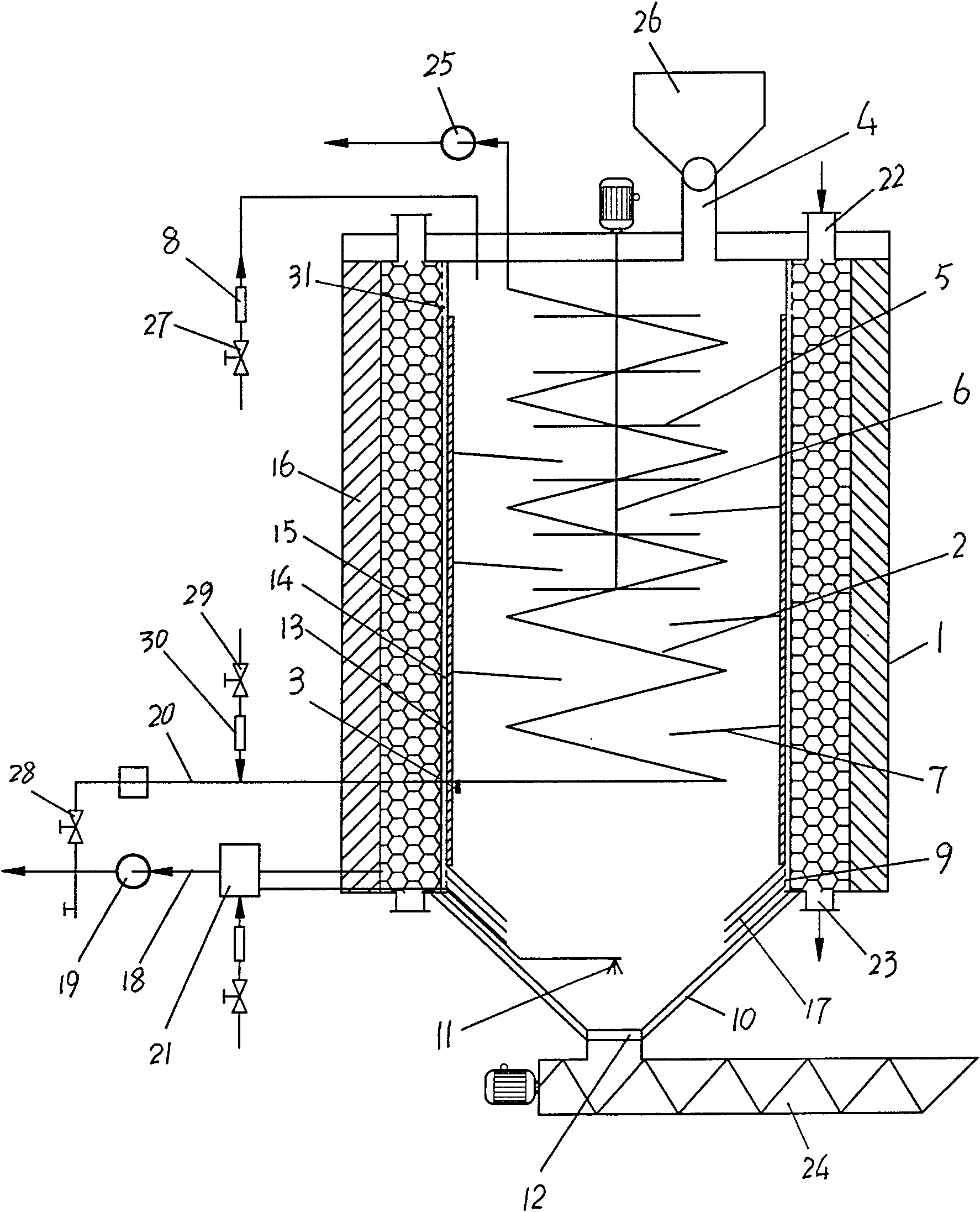
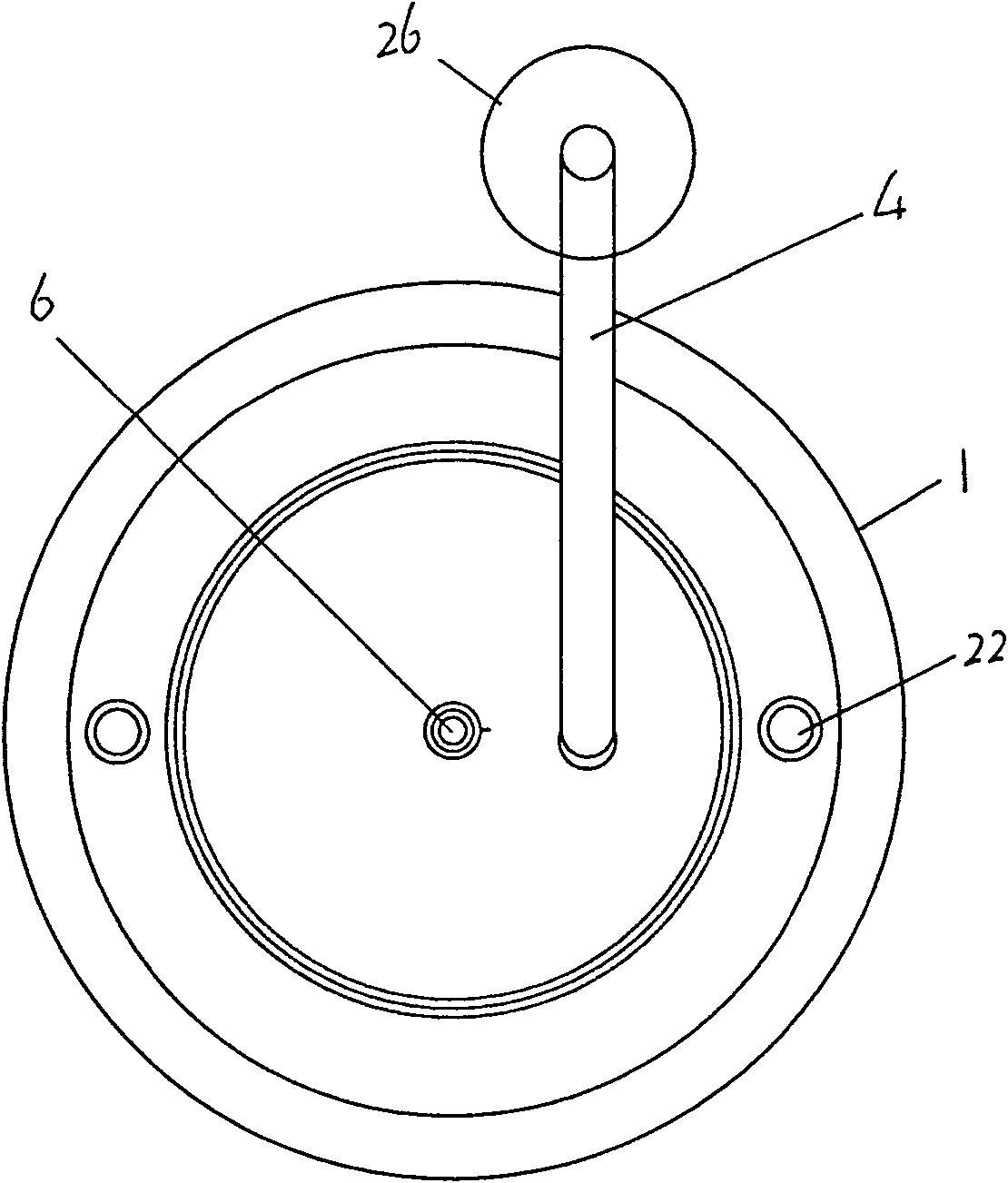
[0029] In this embodiment, the integration of biomass gasification and tar cracking is set. Such as figure 1 and figure 2 As shown, a cylindrical furnace body 1 is adopted, and a serpentine internal combustion pipeline 2 is arranged inside the cylindrical furnace body 1. The entrance of the serpentine internal combustion pipeline 2 is located at the bottom of the cylindrical furnace body 1, and its outlet is from the cylinder The top of the furnace body 1 is extended to the outside of the furnace body, and the igniter 3 is located at the entrance of the internal combustion pipeline 2;

[0030] Above the cylindrical furnace body 1, a screw feed mechanism 4 is arranged, and the screw feed port is located at the top eccentric position of the cylindrical furnace body 1, and on the central axis position of the cylindrical furnace body 1, a The stirring shaft 6 of the stirring blade 5 is provided with a multi-layer baffle 7 along the circumferential surface of the side wall on th...


PUM


Abstract

Biomass tar catalytic cracking device is characterized by adopting a cylindrical furnace body with a conical bottom connected to the bottom. The side wall of the cylindrical furnace body is set as a jacket structure, and the jacket is a high temperature resistant furnace wall from the inside to the outside. , gas channel, catalyst bed, insulation layer and outer wall of the furnace; the gas flow channel drawn from the furnace is: a rectifier located at the bottom of the cylindrical furnace body and guided to the bottom of the gas channel along the slope of the conical furnace bottom. The plate is the inlet, the top outlet of the gas channel leads to the catalyst bed through the top filter, the gas outlet is located at the bottom of the catalyst bed, and the gas outlet is connected to the gas outlet outside the furnace, and the gas pipeline is connected to the gas storage tank through the induced draft fan. The invention keeps the catalyst bed at a high temperature all the time, the cracked high-temperature gas directly enters the catalyst bed, the tar catalytic cracking efficiency is high, and the tar adhesion and blockage of the gas transmission pipeline system is effectively avoided.

Description

technical field [0001] The invention relates to a biomass tar catalytic cracking device. Background technique [0002] Biomass is a kind of renewable energy with abundant reserves, which can be used as an alternative energy source to achieve CO 2 Zero emission, and the low content of S and N in it can greatly reduce the greenhouse effect and environmental pollution. [0003] Aiming at the problem that the gas formed by biomass gasification contains a lot of tar, there are currently two solutions: one is water washing treatment, and the tar in the gas is transferred to the aqueous solution. Although this method is simple, the purification efficiency of the gas is also high. Higher, but will produce a large amount of tar-containing wastewater, which is difficult and costly to treat, causing secondary pollution, and will affect the efficient operation of the gasification system, which will eventually lead to higher gas costs, which is not conducive to the utilization of biomas...

Claims


Application Information

Patent Timeline
Patent Type & Authority Patents(China)
IPC IPC(8): C10G11/00
Inventor 陈天虎朱承柱彭书传何宏平
Owner HEFEI UNIV OF TECH
Why Eureka
Try Eureka