Artificially triggered lightning pneumatic remote-control ignition device for rocket

A technology of ignition devices and rockets, which is applied to rocket launchers, electromagnetic launchers, weapons without explosives, etc., can solve the problems of losing the chance of successfully triggering mines, and achieve the effect of avoiding false launches and ensuring reliability.

Inactive Publication Date: 2009-12-02
COLD & ARID REGIONS ENVIRONMENTAL & ENG RES INST CHINESE
View PDF5 Cites 0 Cited by
  • Summary
  • Abstract
  • Description
  • Claims
  • Application Information

AI Technical Summary

Problems solved by technology

Pull cord switch remote ignition is safe, reliable, and low in cost, but because there is a distance of about 80 meters between the launch control point and the launch point, such a long-distance installation of the pull rope has strict requirements on the terrain, and the distance between the two points must be flat , there should be no obstacles or bushes, so that the pull rope can be pulled smoothly, and the rocket that induces lightning can be lifted into the sky
It has been found from practice that no matter it is wireless remote control or pull rope remote control, they all have a common shortcoming, that is, after each successful lightning induction, the high voltage of the lightning caused by it will put the rocket on the rocket to be launched through the ignition wire. Shot into the air, thus losing the next chance to successfully trigger the mine

Method used


Image

  • Artificially triggered lightning pneumatic remote-control ignition device for rocket
  • Artificially triggered lightning pneumatic remote-control ignition device for rocket

Examples


Embodiment Construction

[0014] Below, the present invention will be further described in conjunction with accompanying drawing:

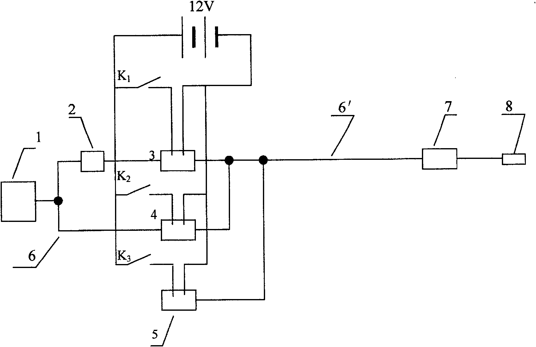
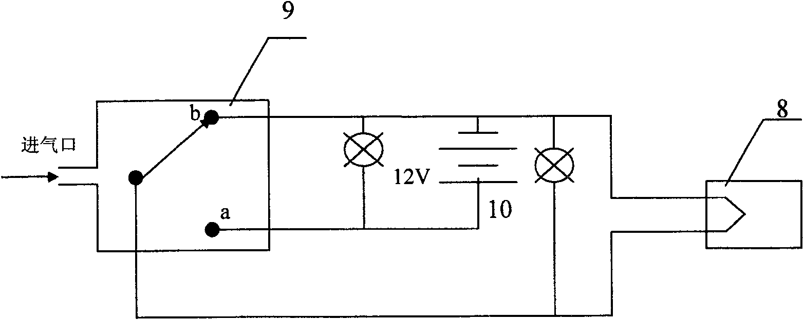
[0015] see figure 1 . A pneumatic remote control rocket ignition device for manual lightning induction is composed of air source 1, (air compressor model: ZB-0.1 / B type) pre-inflated pressure limiting valve 2, pre-inflated solenoid valve 3, ignition solenoid valve 4, reset Solenoid valve 5, air pipe 6,6 ', pneumatic switch igniter 7, rocket electric explosion tube 8 form. The gas output from the gas source 1, one of which is connected to the pre-inflated pressure limiting valve 2 through the gas pipeline 6, and then connected to the pre-charge solenoid valve 3 through the gas pipeline, and the other is directly connected to the ignition solenoid valve 4 through the gas pipeline 6, and reset Solenoid valve 5 three-way merges in phi is 6mm, and L is the long air pipe 6 ' of 80m, is connected with pneumatic switch igniter 7 again. The output of the pneumatic switch igniter...


PUM


Abstract

The utility model relates to a pneumatic remote-controlled rocket ignition device for artificial lightning induction. The gas output from the gas source, one of which is connected to the pre-inflated pressure limiting valve through the gas pipeline, and then connected to the pre-charge solenoid valve through the gas pipeline, and the other is directly connected to the ignition solenoid valve through the gas pipeline, and the reset solenoid valve is connected in three ways. The air pipe is connected with the pneumatic switch igniter. The output of the pneumatic switch igniter is connected with the electric squib of the rocket. The pre-charge solenoid valve, ignition solenoid valve and reset solenoid valve are connected with 12V DC power supply, and the opening and closing of the pre-charge solenoid valve, ignition solenoid valve and reset solenoid valve are respectively controlled by K1, K2 and K3. One contact a of the pneumatic switch in the pneumatic switch igniter is connected to the ignition power supply, and the other contact b is connected to the electric squib of the rocket. The present invention uses compressed air as the signal transmission medium, so that there is no wire connection between the emission control point and the emission point, and avoids the danger that lightning may reach the emission control point along the wire after successful lightning induction. Compared with wireless remote control and pull cord switch remote control, it has no electromagnetic interference and special requirements for terrain, and it is undoubtedly the safest and most reliable way to ignite and launch artificially induced lightning rockets.

Description

technical field [0001] The invention relates to a rocket ignition device which utilizes pneumatic remote control to artificially trigger lightning. Background technique [0002] Artificially induced lightning (also known as artificially triggered lightning, artificially induced lightning, referred to as artificially induced lightning) is a new technology developed in recent decades. It refers to the use of certain equipment and devices (generally It is a small rocket carrying a thin steel wire with a length of several hundred meters and a diameter of 0.2 mm to the thunderstorm cloud) to trigger lightning. [0003] Artificially induced lightning is of great significance in the lightning research of lightning physics. The artificial lightning launching control device is the most important component in the artificial lightning system. For decades, scientific and technological personnel have made unremitting efforts and carried out fruitful explorations in the work of triggeri...

Claims


Application Information

Patent Timeline
Patent Type & Authority Patents(China)
IPC IPC(8): F41F3/04F41B6/00
Inventor 肖庆复刘欣生郄秀书
Owner COLD & ARID REGIONS ENVIRONMENTAL & ENG RES INST CHINESE
Why Eureka
Try Eureka