Laser oscillation device

An oscillation device, laser technology, applied in lasers, laser parts, phonon exciters, etc., can solve problems such as inability to measure distance correctly, achieve simple structure, and prevent deterioration or damage.

Inactive Publication Date: 2009-12-09
KK TOPCON
View PDF7 Cites 0 Cited by
  • Summary
  • Abstract
  • Description
  • Claims
  • Application Information

AI Technical Summary

Problems solved by technology

[0012] Some laser devices require linearly polarized laser light. For example, in light wave distance measuring devices, the distance is calculated according to the phase difference between the reference light and the reflected light. When the emitted laser light itself has a phase difference, there is a problem that the distance cannot be measured correctly. question

Method used


Image

  • Laser oscillation device
  • Laser oscillation device
  • Laser oscillation device

Examples


Embodiment Construction

[0037] Preferred embodiments of the present invention will be described below with reference to the drawings.

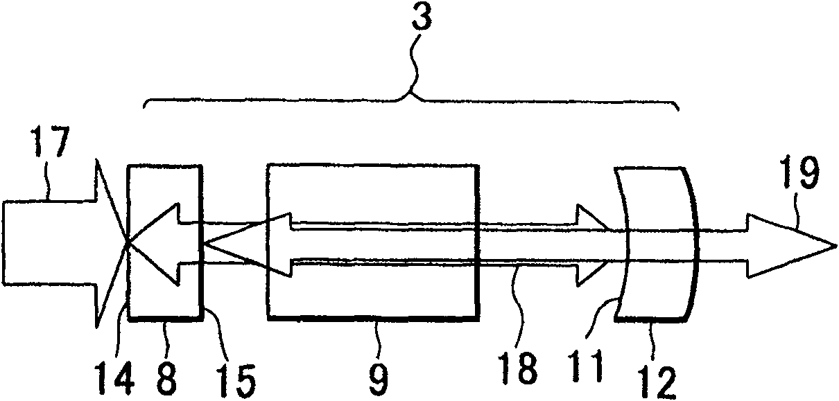
[0038] First refer to figure 1 The outline of the present invention will be described. exist figure 1 In , parts equivalent to those shown in FIG. 19 are denoted by the same symbols. in addition, figure 1 The light-emitting part 2 is omitted in .

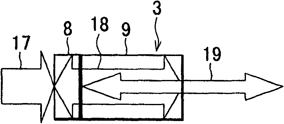
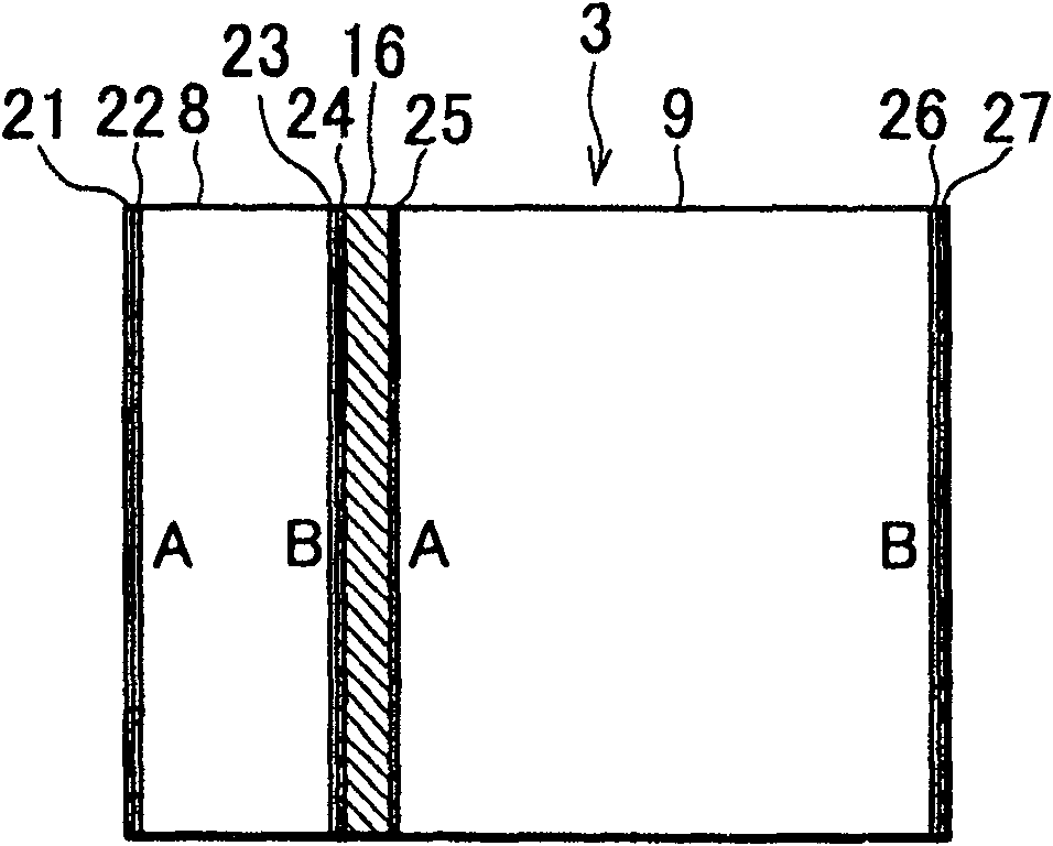
[0039] The optical resonance unit 3 includes a laser crystal 8 , a second harmonic wavelength conversion crystal 9 , and a concave mirror 12 .

[0040] A first dielectric reflection film 14 is formed on the incident surface of the laser crystal 8 , a third dielectric reflection film 15 is formed on the emission surface of the laser crystal 8 , and a second dielectric reflection film 11 is formed on the concave mirror 12 .

[0041]The first dielectric reflective film 14 is highly transmissive to the excitation light 17 (laser light from the light emitting portion 2 (see FIG. 19 )), and highly reflective to the oscillat...


PUM


Abstract

The present invention provides a laser oscillation device, comprising: a laser crystal as an optical crystal and oscillating incident excitation light into a fundamental wave; a wavelength conversion crystal for second harmonic that converts the fundamental wave into a second harmonic; and A reflective film formed on the exit end face of the laser crystal or the incident end face of the second harmonic wavelength conversion crystal reflects the second harmonic and does not pass through the laser crystal.

Description

technical field [0001] The present invention relates to a laser oscillator using a semiconductor laser as an excitation source. Background technique [0002] FIG. 19 shows an LD-pumped solid-state laser that oscillates at one wavelength as an example of the laser oscillator 1 . [0003] In FIG. 19, 2 is a light emitting part, and 3 is an optical resonance part. Above-mentioned light-emitting part 2 comprises LD illuminator 4 and condenser lens 5, and above-mentioned optical resonance part 3 comprises: the first optical crystal (laser crystal 8) that is formed with the first dielectric reflection film 7, the second optical crystal (nonlinear optical crystal (NLO) (wavelength conversion crystal 9 for the second harmonic wave), the second concave mirror 12 formed with the second dielectric reflection film 11, pumps the laser light in the above-mentioned optical resonance part 3, and makes the laser light generate Resonate, amplify it and output it. In addition, Nd:YVO4 is us...

Claims


Application Information

Patent Timeline
Patent Type & Authority Patents(China)
IPC IPC(8): H01S3/00H01S3/05H01S3/109
Inventor 江野泰造后藤义明籾内正幸
Owner KK TOPCON
Why Eureka
Try Eureka