A dual-mode compact overmode directional coupler

A directional coupler, compact technology, applied in the direction of waveguide devices, circuits, connecting devices, etc., can solve the problems of single working mode, large device volume, large insertion loss, etc., and achieve simple overall design, reduce processing difficulty, high The effect of directional output

Active Publication Date: 2021-02-02
UNIV OF ELECTRONICS SCI & TECH OF CHINA
View PDF3 Cites 0 Cited by
  • Summary
  • Abstract
  • Description
  • Claims
  • Application Information

AI Technical Summary

Problems solved by technology

[0004] Aiming at the problems of existing high-power directional couplers such as single working mode, large device volume, and large insertion loss, the present invention proposes a compact high-power directional coupler, which realizes linearly polarized waves and circularly polarized waves within a wide frequency band. power monitoring

Method used


Image

  • A dual-mode compact overmode directional coupler
  • A dual-mode compact overmode directional coupler
  • A dual-mode compact overmode directional coupler

Examples


Embodiment Construction

[0028] The specific implementation of the present invention will be described below by taking the Ku-band compact dual-mode directional coupler as an example in conjunction with the accompanying drawings.

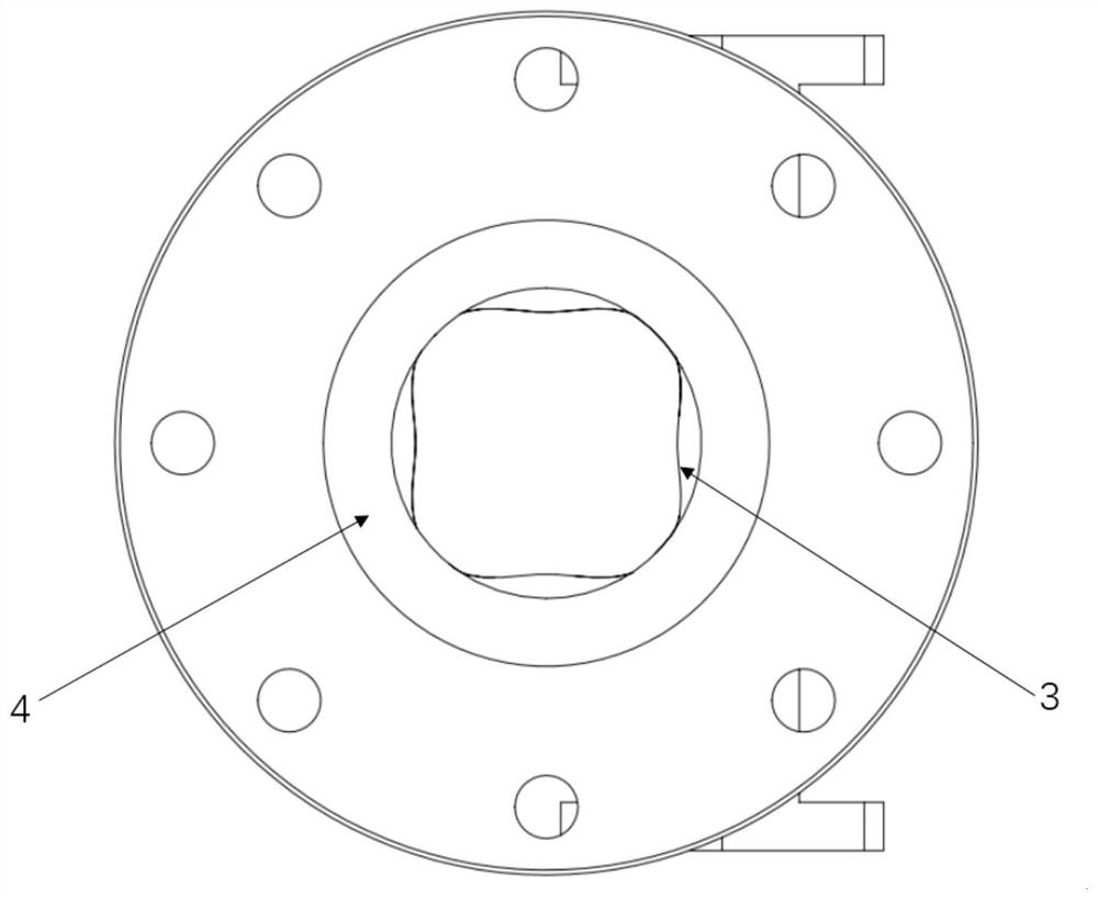
[0029] In this embodiment, the radius of the circular waveguide in the input / output transition section is 16 mm.

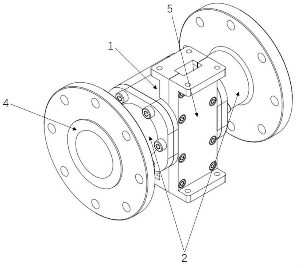
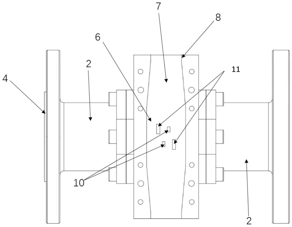
[0030] like figure 1 , Figure 4 , Figure 5 As shown, the inventive directional coupler includes a coupling part 1 and an input / output transition section 2 placed symmetrically at both ends.

[0031] The input / output transition section 2 is a circular waveguide-like circular waveguide conversion structure, and its conversion method is a linear transition to realize the TE between the circular waveguide and the similar circular waveguide. 11 - quasi TE 11 Mode conversion, the length of each segment is 50mm. The transition section and the front and rear connectors are connected through waveguide flanges. In order to ensure the coaxial connection, the connec...


PUM


Abstract

The invention discloses a dual-mode compact overmode directional coupler, which belongs to the technical field of high-power microwaves. The directional coupler includes a coupling part and an input / output transition section symmetrically placed at both ends thereof; the input / output transition section is a circular waveguide-like circular waveguide conversion structure, realizing circular waveguide TE 11 Mode‑Like Circular Waveguide Quasi-TE 11 Mode conversion between modes; the coupling part includes a coupling hole, a quasi-circular waveguide as a microwave main channel, and a sub-waveguide, and the quasi-circular waveguide is connected to the sub-waveguide through the coupling hole. The invention realizes high directional output under the premise of satisfying the coupling degree by adopting the double-row coupling slots placed symmetrically in the center. It has dual-mode working characteristics, that is, it can monitor both circularly polarized and linearly polarized incident waves without changing the polarization state of the incident beam, and has a wide range of applications. The overall design of the structural directional coupler of the present invention is simple and compact, and the processing difficulty is effectively reduced.

Description

technical field [0001] The invention belongs to the technical field of high-power microwaves, and in particular relates to a waveguide directional coupler used for energy monitoring and analysis in a high-power microwave transmission system. Background technique [0002] In order to monitor the output power of a high-power microwave system on-line, it is necessary to develop a high-performance overmode waveguide directional coupler. Generally speaking, the high performance of high-performance directional couplers is embodied in the appropriate coupling degree, high isolation and high directivity. At the same time, considering that there are different polarization states (linear polarization or circular polarization) of electromagnetic waves on the high-power transmission line, the directional coupler also needs to have dual-mode operating characteristics, that is, the incidence of linearly polarized waves and circularly polarized waves Both cases work. In addition, in orde...

Claims


Application Information

Patent Timeline
Patent Type & Authority Patents(China)
IPC IPC(8): H01P5/18
CPCH01P5/181
Inventor 吴泽威王敏行周秋辉刘国蒲友雷蒋伟罗勇
Owner UNIV OF ELECTRONICS SCI & TECH OF CHINA
Why Eureka
Try Eureka