Inner-expanded-type solar vacuum heat-collecting pipe

A trough solar and vacuum collector tube technology, applied in solar collectors, solar collector safety, solar thermal energy and other directions, can solve the problems of complex process, difficult to withstand high temperature, limited length, etc., to simplify installation and connection Structure, to meet the high-power heat collection, to maintain the effect of long-term sealing

Inactive Publication Date: 2009-12-16
HOHAI UNIV
View PDF11 Cites 0 Cited by
  • Summary
  • Abstract
  • Description
  • Claims
  • Application Information

AI Technical Summary

Problems solved by technology

However, practice has proved that this kind of vacuum heat collecting tube with bellows as the inner tube is concentrated on the glass tube, obviously insufficient in strength and rigidity, limited in length, and has a large flow resistance, which cannot meet the needs of high-power heat collection.
In addition, its structure relying on the metal bowl as a transition piece is not only complicated in process, but also unreliable in connection with the glass tube, difficult to withstand high temperature, and prone to leakage

Method used


Image

  • Inner-expanded-type solar vacuum heat-collecting pipe
  • Inner-expanded-type solar vacuum heat-collecting pipe
  • Inner-expanded-type solar vacuum heat-collecting pipe

Examples


Embodiment 1

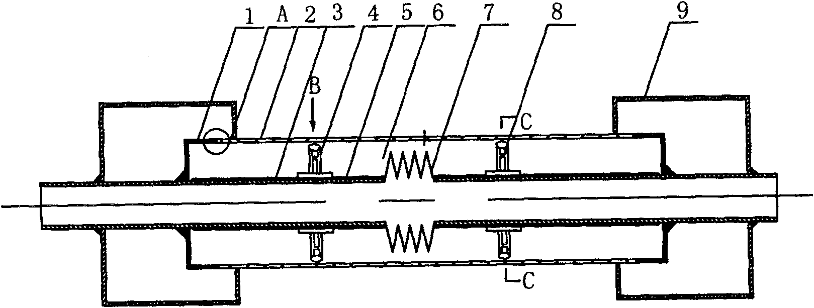
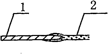
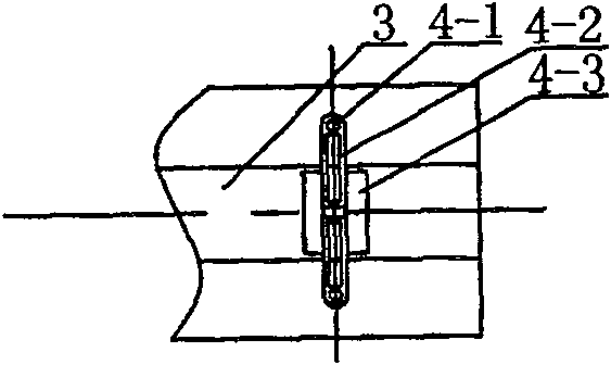
[0017] The internal expansion tank type solar vacuum heat collecting tube of the present embodiment is as figure 1 As shown, its structure is that the glass tube 2 is set on the central metal tube 3, and the getter is placed in the tube to reach and maintain the 10 in the tube. -2 The vacuum degree of Pa forms the vacuum layer 6. The surface of the metal pipe is coated with a solar light absorbing coating 5 . The metal pipe 3 is split in the middle, and a wave expansion joint 7 is added for sealing welding, so as to compensate the expansion difference between the glass pipe 2 and the metal pipe 3 after the temperature rises. Self-centering supports 4 and 8 are respectively installed in the middle of the two sections of metal pipe 3, and its specific structure is as follows image 3 and Figure 4 As shown, the self-centering support is composed of an arc support seat 4-3, an elastic support piece 4-2, and a contact head 4-1. The arc radius of the arc support seat 4-3 matches...


PUM


Abstract

The present invention relates to an inner-expanded-type solar vacuum heat-collecting pipe, belonging to the solar energy heat-collecting facility technical field. The vacuum heat-collecting pipe includes a guard glass tube mounted on the middle metal tube. The outside of the metal tube is coated with the decalescent layer. The middle of the metal tube is broken in a tight connection through the corrugated type expansion joint. The two ends of the glass tube are end sealed with the outreaching end of two sects of metal tube through the kovar alloy. The space between the glass tube and the metal tube and the corrugated type expansion joint are vacuumized to form a vacumm layer. The middle of the metal tube and the glass tube are respectively arranged with a self centering support. The invention digests the swelling amount of the metal tube larger than that of the glass tube to simplify the erection joint structure; meanwhile, the invention has adequate strength and rigidity, which is convenient for the system to install and assemble, especially suitable for the occasions with high temperature and high power solar heat to generate electricity.

Description

technical field [0001] The invention relates to a vacuum heat collection tube, in particular to a structural improvement of the vacuum heat collection tube used in a solar heat utilization system, and belongs to the technical field of solar heat collection facilities. Background technique [0002] The vacuum heat collector is the core device in the solar heat utilization system. The typical structure of the existing vacuum heat collecting tube is as described in Chinese Patent Application No. 95117947. The outer glass tube is set on the metal tube in the middle, and the two ends are sealed and connected. To prevent heat loss, the metal pipe is coated with a heat-absorbing coating to absorb the heat of the sun. The problem in the use of this type of heat collecting tube is: because the expansion coefficient of the metal tube is much larger than that of the glass tube, when the temperature is high, the expansion of the metal tube cannot be digested in the heat collecting tube...

Claims


Application Information

Patent Timeline
Patent Type & Authority Patents(China)
IPC IPC(8): F24J2/05F24S10/40
CPCY02E10/44F24J2/055F24J2/4636F24S10/45F24S40/80
Inventor 王军张耀明刘德有
Owner HOHAI UNIV
Why Eureka
Try Eureka