Leaded light image amplification screen

A screen and image technology, applied in the video field, can solve the problems of high manufacturing cost, increased optical loss of optical fiber, rising splicing cost, etc., and achieve the effect of good integrity, good viewing effect, and elimination of physical seams

Active Publication Date: 2009-12-16
BEIJING FANGRUI BOSHI DIGITAL TECH
View PDF8 Cites 1 Cited by
  • Summary
  • Abstract
  • Description
  • Claims
  • Application Information

AI Technical Summary

Problems solved by technology

The inventors of patents 200410091097.8 and 200410091098.2 introduced a method of using optical fiber to eliminate splicing gaps, which belongs to the application idea of ​​optical fiber in the field of light guide and image guide. Its basic components are image segmentation module, image translation module and image restoration module. The module combination The use of conventional splicing methods will inevitably result in the modularization of the image, forming new splicing seams, and destroying the integrity of the image. The use of high-precision splicing methods will cause a sharp increase in splicing costs, and the technology of eliminating splicing gaps will be added. Difficulty of Implementation and Difficulty of Promotion
The inventor of the patent CN1099175A introduced a method of using optical fiber to make a flat right-angle TV, which also belongs to the application idea of ​​optical fiber in the field of light guide and imaging. The difficulty in making a special optical fiber with a thin end and a thick end with different cross-sectional areas at both ends is that the manufacturing cost of making optical fibers with the same specification and different cross-sectional areas at both ends is too high and the inventor did not consider that the diameter of the optical fiber will increase. Core issues such as light loss in the process of optical fiber light guiding and the impact on screen viewing angle and screen gain

Method used


Image

  • Leaded light image amplification screen
  • Leaded light image amplification screen
  • Leaded light image amplification screen

Examples


Embodiment 1

[0023] Example 1: Press Figure 7 Production of mirror-changing optical fibers with one end thinner and one end thicker. The length of the optical fiber is 30-200mm. After the light layer, the light-receiving surface is formed. A light guide screen is formed by bonding the front light-transmitting layer and the rear-end light-transmitting layer.

Embodiment 2

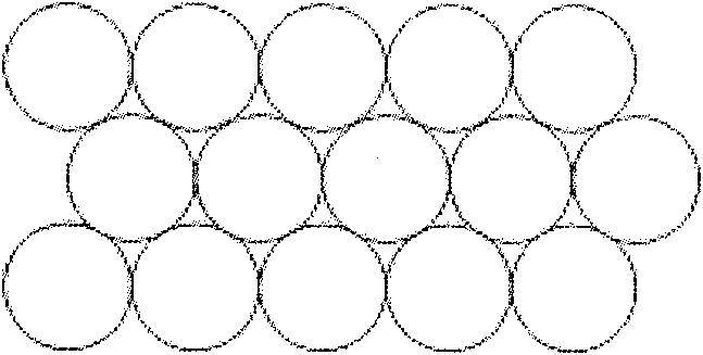
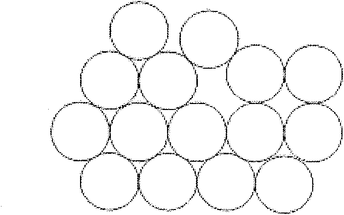
[0024] Example 2: Press Figure 6 Produce uniform-diameter optical fibers with micromirrors, the length of the optical fiber is 30-200mm, the light-receiving surface is piled up in a dense stacking manner, and the light-receiving surface is tightened and bonded according to the geometric size of the light source on the light-receiving surface, and the light-receiving surface is cut, polished, polished, pasted, and the front end is transparent After the layer, the light-receiving surface is formed. A light guide screen is formed by bonding the front light-transmitting layer and the rear-end light-transmitting layer.

Embodiment 3

[0025] Embodiment 3: stick the optical fiber on the back-end light-transmitting layer with a micromirror, clamp and stick the optical fiber on the light-receiving surface according to the geometric size irradiated by the light source on the light-receiving surface, cut, polish, polish, and paste the front end of the light-receiving surface A different light image magnification screen is formed behind the light-transmitting layer.


PUM


Abstract

A light-guiding image magnification screen, which is composed of four layers: a front light transmission layer, an optical fiber transmission layer, a micromirror layer and a rear light transmission layer. The microlens layer is the image magnification lens, and the micromirror layer is directly attached to the fiber optic head At the top, the diameter of the optical fiber of the optical fiber conduction layer is uniform or variable in diameter; according to the size of the non-image frame around the screen, it is designed as a trapezoid with a thickness of 5-100 mm, forming a splicing frame for connection with the back of the screen. It does not affect the image transmission, the cross-sectional area is large on one side and small on the other. In the thickness direction, it is a trapezoidal light-guiding magnifying imaging screen, so as to eliminate the screen splicing gap. The advantage is that the physical seam is completely eliminated, and the optical seam can be reduced to 0-0.2mm to ensure the continuity, integrity and good viewing effect of the stitched image.

Description

technical field [0001] The invention belongs to the field of video technology, such as video seamless splicing technology, video large-screen splicing is suitable for video monitoring, combat command, simulation, TV stations, exhibitions, large-scale public demonstrations and other places, and has a wide range of uses. technical background [0002] At present, the splicing modes with small video splicing gaps on the market are mainly rear projection and plasma splicing. The projected types include DLP optical machine rear projection, which is limited by the brightness of the optical machine. The main sizes are 50 inches, 60 inches, and 67 inches. inch, the splicing gap is about 1.5 mm; the second is super large screen splicing, the screen size is generally 84 inches, 100 inches, 120 inches, 150 inches, and the screen splicing gap is generally about 5 mm; the third is CRT rear projection splicing Mode, limited by the brightness of the CRT projection gun, the size of the gener...

Claims


Application Information

Patent Timeline
Patent Type & Authority Patents(China)
IPC IPC(8): G02B6/06G02B6/04G09F9/305
Inventor 白建荣樊胜利李洪林张永玲颜磊
Owner BEIJING FANGRUI BOSHI DIGITAL TECH
Why Eureka
Try Eureka