
Sound absorbing and insulating barrier

A technology for sound absorption and insulation, which is applied in the fields of sound absorption, vibration reduction device and sound insulation, can solve the problems of fatigue damage, weak anti-vibration ability and poor rigidity of sound absorption and insulation panels, and achieves economical and environmental protection. Excellent, strong wind pressure resistance, improved effect

Active Publication Date: 2009-12-30
QINGDAO CREATE ENVIRONMENT CONTROL TECH
View PDF8 Cites 0 Cited by
  • Summary
  • Abstract
  • Description
  • Claims
  • Application Information

AI Technical Summary

Problems solved by technology

With the acceleration of people's life rhythm, the speed of motor vehicles is getting higher and higher. Many passenger rail vehicles have been speeded up to 200-250 km / h, and will even be speeded up to 300-350 km / h in the future. However, the suction partition currently used Due to the functional and economical requirements and the limitations of the installation structure, the sound barrier is usually made of light weight, large format, poor rigidity, and weak anti-vibration ability. When the vehicle passes at a low speed, it can meet the use requirements. But when the vehicle passes by at high speed, due to the change of air pressure, the alternating exciting force of pulling force and suction force will be formed, especially the entering and exiting wind pressure formed when the front of the vehicle enters and the rear of the vehicle leaves, causing strong vibration of the sound-absorbing barrier
On the one hand, the poor rigidity and small damping of the sound-absorbing and insulating panels will be amplified due to the resonance amplitude, and the number of stress cycles of each component will increase. Over time, it is easy to cause fatigue damage to the sound-absorbing and insulating panels; on the other hand, this This kind of strong vibration will cause great damage to the joints of the frame legs of the sound-absorbing barrier and even the bridges, road foundations or piers connected to it, such as breaking the joints of the legs, loosening the connecting bolts, and cracks in the concrete at the joints Even stripping, etc., seriously affect the service life of the sound-absorbing and insulating barrier, not only causing huge economic waste, but even threatening traffic safety and the safety of road infrastructure

Method used


Image

  • Sound absorbing and insulating barrier
  • Sound absorbing and insulating barrier
  • Sound absorbing and insulating barrier

Examples


Embodiment 1

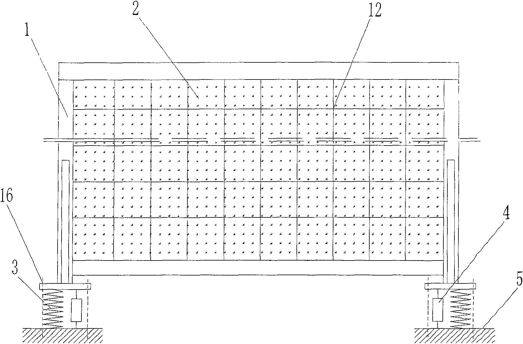
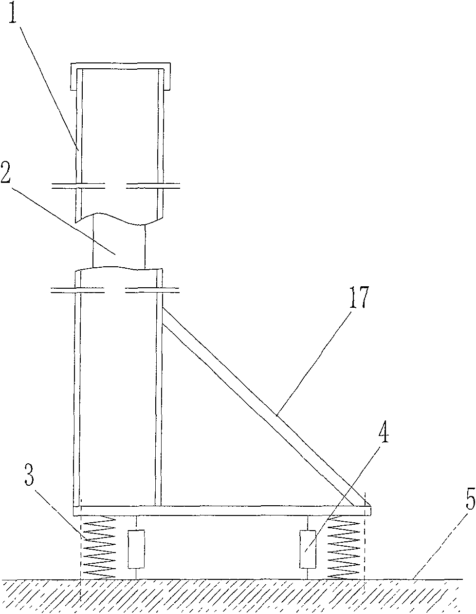
[0026] Such as figure 1 , figure 2 The shown sound absorption and insulation barrier of the present invention includes a support frame 1 and a sound absorption and insulation panel 2. The sound absorption and insulation panel 2 is arranged in the support frame 1, and an elastic element is arranged in parallel between the support frame 1 and the base 5. And the damping element, wherein the elastic element is a spring 3, and the damping element is a damper 4. The support frame 1 and the base 5 are pre-tightly connected together by using anchor bolts 16 (not specifically shown in the figure) preset in the base 5 . In order to strengthen the bending rigidity of the bottom of the supporting frame, the lower part of the supporting frame is provided with oblique reinforcing ribs 17, so that the lower part of the supporting frame forms triangular outriggers.

[0027] When the external exciting force formed by vehicles passing or wind blowing acts on the sound-absorbing barrier, due...

Embodiment 2

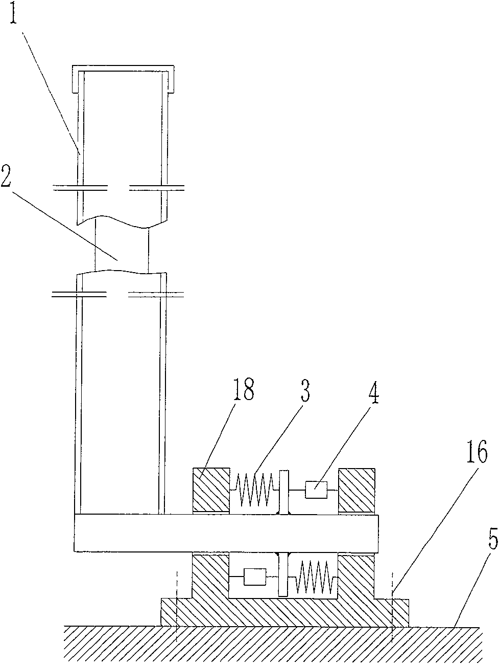
[0034] Such as image 3 The difference between the sound-absorbing and insulating barrier of the present invention as shown in Embodiment 1 is that a guiding device guide support 18 is provided between the legs of the support frame 1 of the sound-absorbing and insulating barrier and the base 5, and a guide support 18 is provided on the guide support 18. The horizontal guide hole in the normal direction of the sound-absorbing and insulating panel enables the legs of the support frame to move horizontally relative to the guide support 18, and the corresponding spring 3 and damper 4 are also arranged horizontally between the support leg and the guide support 18 , The guide support 18 is fixedly connected with the base 5 with bolts.

[0035] After the sound-absorbing and insulating panel 2 bears the external excitation force, it drives the support frame 1 to elastically translate along the normal direction of the sound-absorbing and insulating panel, and its inertial mass balances...

Embodiment 3

[0038] Such as Figure 4 The difference between the sound-absorbing and insulating barrier of the present invention as shown in Embodiment 1 is that a laminated rubber bearing 6 is arranged between the support frame 1 and the base 5, such as the Chinese patent No. ZL3112549.2 announced on September 7, 2005. The vibration-isolation bearing described in the patent can be regarded as an integration of elastic elements and damping elements.

[0039] The laminated rubber support 6 has great rigidity in the vertical direction, but has good elasticity in the horizontal direction, so it acts as a guide in the horizontal direction. Because it can achieve large horizontal shear deformation and limit the swing of the sound-absorbing and insulating barrier, it has guiding function, elastic function and damping function at the same time. Therefore, when the sound-absorbing and insulating barrier is subjected to external excitation force, the laminated rubber bearing 6. Large horizontal el...


PUM


Abstract

The invention relates to a shield besides road to adsorb noise, which comprises a sound adsorption shield and a support frame, wherein the shield plate and the support frame or / and support frame and the base are connected via flexible element or / and damping element, the flexible element and the damping element can be serially, parallel or integrally connected. The invention can improve sound adsorption ability and protect the base, with long service life, less increase on the load of road, and high safety or the like.

Description

technical field [0001] The invention relates to the fields of noise control and vibration control, and belongs to a sound absorption, sound insulation and vibration reduction device, in particular to a barrier for absorbing and isolating noise on both sides of a road and a railway. Background technique [0002] Various vehicles will generate strong noise when running on roads or railways. In order to reduce the impact of noise on production facilities, buildings and people's lives, suction absorbers are usually installed next to roads or railways that pass through bridges, residential areas or industrial areas. Sound insulation barrier to achieve sound insulation and noise reduction. With the acceleration of people's life rhythm, the speed of motor vehicles is getting higher and higher. Many passenger rail vehicles have been speeded up to 200-250 km / h, and will even be speeded up to 300-350 km / h in the future. However, the suction partition currently used Due to the functio...

Claims


Application Information

Patent Timeline
Patent Type & Authority Patents(China)
IPC IPC(8): E01F8/00
CPCE01F8/0023
Inventor 李凤娥
Owner QINGDAO CREATE ENVIRONMENT CONTROL TECH
Learn More