Full-hydraulic multifunctional driller for gas extraction, drainage and discharge

A multi-functional, fully hydraulic technology, used in gas discharge, rotary drilling rigs, earth-moving drilling, etc., can solve the problems of many processes, poor guide rail, unreliable clamping, etc., and achieve high guiding accuracy, strong rigidity and convenient operation. Effect

Inactive Publication Date: 2009-12-30
CHONGQING UNIVERSITY OF SCIENCE AND TECHNOLOGY
View PDF5 Cites 0 Cited by
  • Summary
  • Abstract
  • Description
  • Claims
  • Application Information

AI Technical Summary

Problems solved by technology

[0003] 1. When adjusting the working height and inclination angle of the drilling rig, it is necessary to disassemble and assemble the connecting part between the drilling rig frame and the column frame or between the frame and the support rod, which is time-consuming and laborious, and cannot realize online stepless adjustment. Seriously affect work efficiency;
[0004] 2. The structure of the guide support mechanism of the power head is too simple. The frame adopts a U-shaped channel steel structure with the opening facing upwards. The upper ends of the U-shaped channel steel are bent vertically outwards to form the guide rail of the carriage. Elastic deformation is easy to occur in the center, which makes the guiding accuracy poor; the upper and lower copper plates of the guide rail are easy to wear, resulting in intermittent increase, and cannot be eliminated and compensated. When the drilling rig is working, the vibration is large, and the drill pipe is easy to break. Can only be replaced offline, which is labor-intensive and time-consuming, affecting work efficiency;
[0005] 3. The chuck is a normally closed structure, and the disc spring is always in a compressed state when it is tightened and loosened. Over time, the disc spring is prone to aging and failure, so that it cannot reliably clamp the drill pipe; in the actual application process During the process, the mud will enter and deposit in the end cover of the cylinder block through the gap between the slip seat and the hollow shaft, causing the disk spring to be stuck by the mud, and the chuck cannot be released normally; the chuck and water The braids are independent of each other. During the drilling operation of the drilling rig, every time a drill pipe is added, it is necessary to perform thread tightening work between the water braid shaft and the newly added drill pipe. When drilling out, the water section needs to be removed; the drill pipe When screwing on and off the water braid shaft through threads, manual assistance is required, there are many processes, the work efficiency is low, the labor intensity of the workers is high, and work-related accidents are prone to occur during operation;
[0006] 4. The hydraulic gripper has a two-claw structure. The housing of the gripper is not only the mounting bracket of the slips, but also the hydraulic cylinder of the piston. The sealing ring of the piston is easy to fail and cause leakage during use. The slips only move from two directions. Acting on the drill pipe, there is less friction between them, resulting in unreliable clamping
The movement of the two slips is difficult to achieve synchronization, which often causes the center formed by the two slips of the holder to be inconsistent with the center of the drilling rig power head, resulting in inconsistent centers between the added drill pipe and the drill pipe clamped by the holder, and difficult alignment. At the same time, It is also easy to damage the connecting threads between the drill pipes, which increases the vibration of the drilling rig and even breaks the drill pipes

Method used


Image

  • Full-hydraulic multifunctional driller for gas extraction, drainage and discharge
  • Full-hydraulic multifunctional driller for gas extraction, drainage and discharge
  • Full-hydraulic multifunctional driller for gas extraction, drainage and discharge

Examples


Embodiment Construction

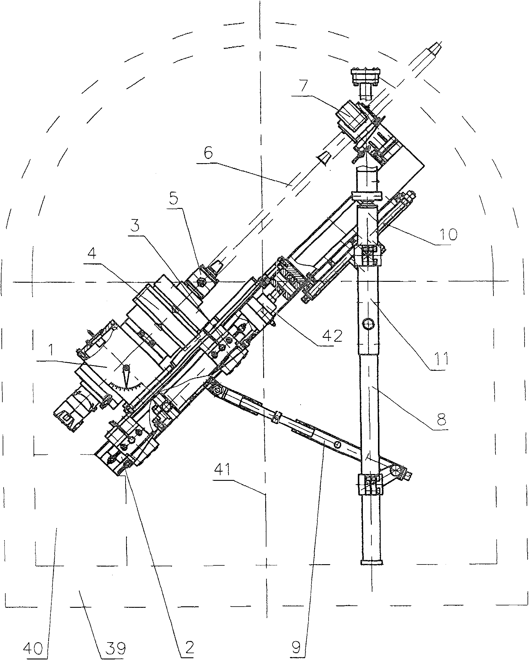
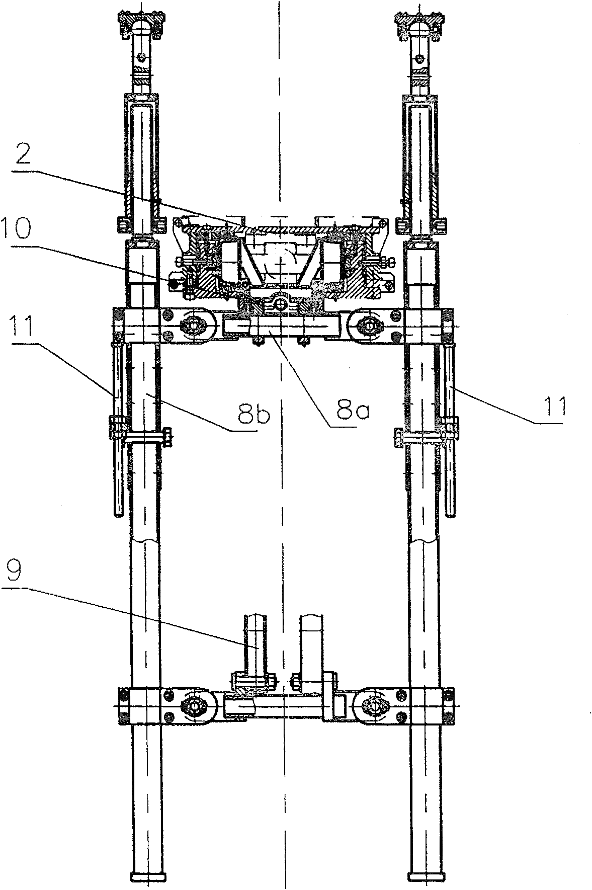
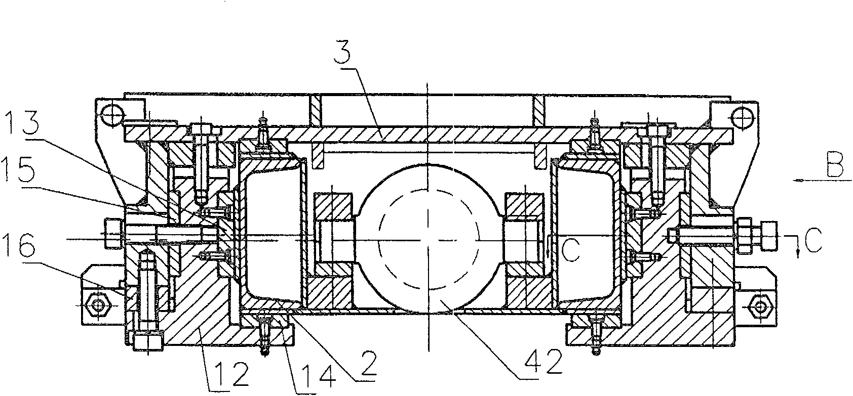
[0020] Such as Figure 1 to Figure 5 As shown, the fully hydraulic gas pumping and discharging multifunctional drilling rig of the present invention has a power head 1, a frame 2, a carriage 3, a chuck 4, a braid 5, a drill pipe 6, a clamper 7, a column frame 8 and a support The rod 9 and the column frame 8 are composed of two left and right columns 8b and a beam 8a. The power head 1 is limited on the guide rail of the frame 2 by the carriage 3. The frame 2 is positioned on the column frame 8 and the support rod 9. The power head 1 The output end is connected with the drill pipe 6 through the chuck 4 and the water braid 5. The frame 2 is connected with the beam 8a of the column frame 8 through the screw nut mechanism 10, and the two ends of the beam 8a of the column frame 8 are connected on the column 8b through the screw nut mechanism 11. The support rod 9 is composed of three sections, and the middle section 9b is Adjust the screw mandrel, and the other two sections 9a, 9c ...


PUM


Abstract

This invention relates to one whole hydraulic oil discharge multi-function drilling machine, wherein, the rack is connected to column frame beam through wire beam screw structure and the column frame beam two ends are connected to column through wire beam; the supportive bar is composed of three sections with middle section is wire bar and other two set with T shape socket; the middle socket and rack outside and down side are set with copper board; the middle socket and drag board limit are set with gap adjust wedge block.

Description

technical field [0001] The invention belongs to the technical field of drilling equipment for soil layers or rocks, and in particular relates to a fully hydraulic gas pumping and discharging drilling rig. Background technique [0002] The gas drainage drilling rig is mainly used for drilling gas drainage holes, grouting fire extinguishing holes, coal seam water injection holes, outburst prevention and pressure relief holes, geological exploration holes or other engineering holes in coal mines. At present, it is used in small and medium cross-section gas drainage tunnels or drilling sites (the cross-sectional area is less than 6.5m 2 , the height is less than 2.5m, and the width is less than 2.8m) The full hydraulic drilling rig is mainly composed of six parts: pump station, power head, frame, column frame, drilling tool and console. During operation, the pump station and the console are placed on the ground, the frame is positioned on the column frame, the power head is lim...

Claims


Application Information

Patent Timeline
Patent Type & Authority Patents(China)
IPC IPC(8): E21B3/00E21B15/00E21F7/00
Inventor 朱新才林顺洪李长江
Owner CHONGQING UNIVERSITY OF SCIENCE AND TECHNOLOGY
Why Eureka
Try Eureka