Lead accumulator

A technology for lead-acid batteries and storage batteries, which is applied in the field of lead-acid batteries and can solve problems such as electrolyte overflow, flying out, and damage to gas discharge functions

Inactive Publication Date: 2009-12-30
GS YUASA INT LTD
View PDF8 Cites 0 Cited by
  • Summary
  • Abstract
  • Description
  • Claims
  • Application Information

AI Technical Summary

Problems solved by technology

In the methods proposed in the above-mentioned patent documents 1 to 3, when the electrolyte level fluctuates and inclines, the electrolyte passes through the gas discharge port connecting the unit cells and the exhaust chamber, and the electrolyte in the unit cells may fly out into the exhaust chamber.
In addition, the electrolyte may overflow from the vent chamber to the outside of the battery when the battery is turned over by mistake
In addition, space cannot be secured on the upper cover side of the centralized exhaust chamber, and the gas discharge function may be impaired, or the filter may fall to the bottom of the centralized exhaust chamber and fail to function as a filter.

Method used


Image

  • Lead accumulator
  • Lead accumulator
  • Lead accumulator

Examples


Embodiment Construction

[0059] Hereinafter, the present invention will be described in detail through one embodiment, but the present invention is not limited to this.

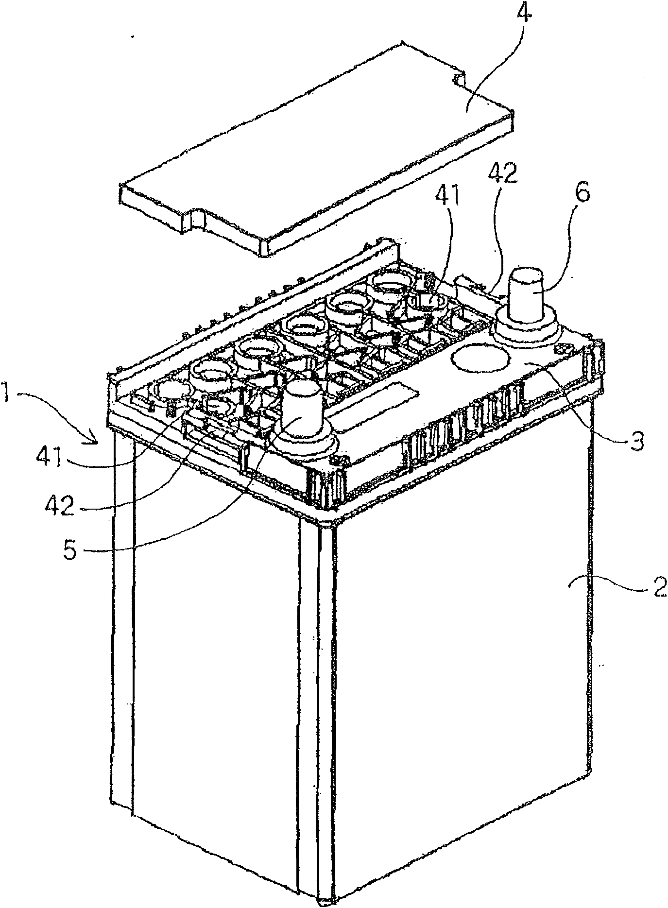
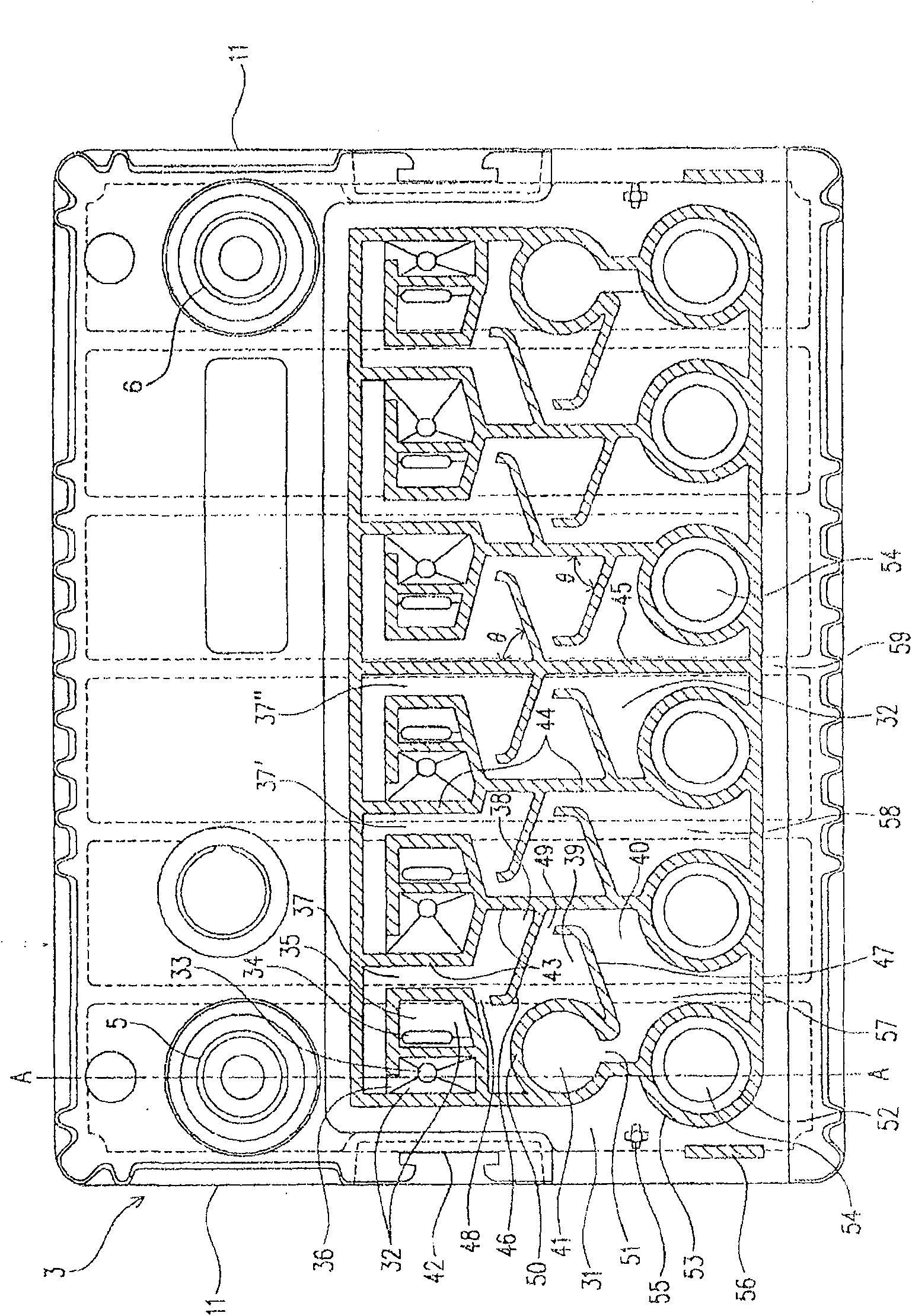
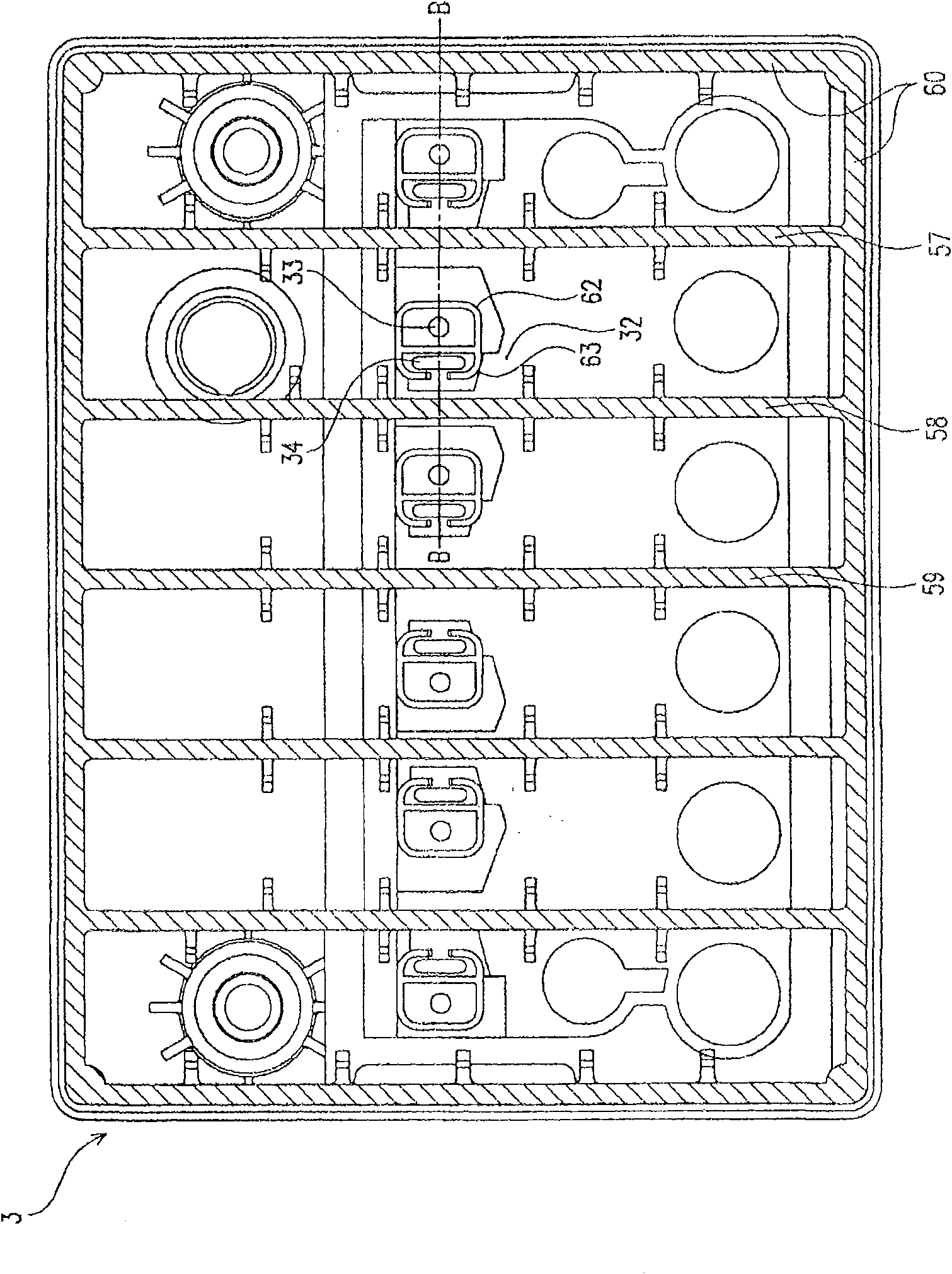
[0060] figure 1 It is a perspective view of the six-cell integrated lead storage battery 1 according to an embodiment of the present invention when viewed obliquely from above. figure 1 2 is the battery case, the inside of which is divided into six unit cells by five partition walls (not shown) arranged in parallel with the short sides of the battery side, and each unit cell is housed by a set of positive plates, negative plates and partitions. An electrode plate group composed of plates and an electrolyte composed of dilute sulfuric acid (not shown). figure 1 3 is the middle cover installed on the upper surface of the battery case 2, and 4 is the upper cover installed in the recess of the middle cover 3. The battery case 2, the middle cover 3, and the upper cover 4 are all polypropylene molded bodies. The upper end of the side wall (...


PUM


Abstract

A lead battery employing a collective exhaust system and exhibiting excellent gas exhaust function and electrolyte leakage preventive function in which the electrolyte does not leak even when the battery turns sideways. In the lead battery equipped with a collective exhaustion mechanism, a partition wall is arranged to surround an opening consisting of an electrolyte circulation opening (33) and a gas exhaust opening (34), a cell communicating subchamber (35) sectioned from exhaust chambers (37, 37', 37'') by the partition wall is provided, and the cell communicating chamber (35) is communicated with the exhaust chambers (37, 37', 37'') through a cut (36) provided on the partition wall, and the cell communicating subchamber (35) is isolated from the exhaust chambers (37, 37', 37'') by the partition wall excepting the cut (36).

Description

Technical field [0001] The present invention relates to a lead storage battery having an exhaust structure that can discharge gas while preventing electrolyte from escaping. Background technique [0002] The exhaust structure of a monolithic lead storage battery with multiple cells is roughly divided into a separate exhaust method and a collective exhaust method. The separate exhaust method is to install an exhaust plug on each unit cell, one side by side In the gas method, the gas discharged from each unit cell is temporarily introduced into the exhaust chamber, and the gas is collected and discharged from the exhaust chamber to the outside. Compared with the separate exhaust method, the collective exhaust method has the advantages of fewer parts, reducing the volume of the upper space of the electrode plate without reducing the battery capacity, and achieving the miniaturization of the battery and reducing the amount of electrolyte leakage. Therefore, it is widely used in lead-...

Claims


Application Information

Patent Timeline
Patent Type & Authority Patents(China)
IPC IPC(8): H01M2/12
CPCH01M10/4228H01M2/38H01M10/06H01M2/12Y02E60/126H01M50/30H01M50/70Y02E60/10
Inventor 山口义彰河田裕泰秋本尚
Owner GS YUASA INT LTD
Why Eureka
Try Eureka