New energy automobile water-cooled condenser

A new energy vehicle and condenser technology, which is applied in the direction of evaporator/condenser, refrigerator, refrigeration components, etc., can solve the problems of poor air cooling effect, unreasonable use of heat, waste of heat, etc., to improve battery life , Reasonable use of heat energy, fast cooling effect

Pending Publication Date: 2018-10-26
苏州赛普瑞新能源科技有限公司
View PDF9 Cites 8 Cited by
  • Summary
  • Abstract
  • Description
  • Claims
  • Application Information

AI Technical Summary

Problems solved by technology

[0004] However, the current condenser has the following disadvantages: 1. The effect of air cooling is poor and the effect is slow; 2. The heat in the high-temperature refrigerant is taken away by the flowing air, resulting in waste of heat, especially in new energy vehicles. In the process, since the power of the car comes from the battery, this part of the heat in the high-temperature refrigerant has not been used reasonably, which has caused the thermal energy management system in the new energy vehicle to be unreasonable and the thermal energy utilization rate is not high

Method used


Image

  • New energy automobile water-cooled condenser
  • New energy automobile water-cooled condenser
  • New energy automobile water-cooled condenser

Examples


Embodiment 1

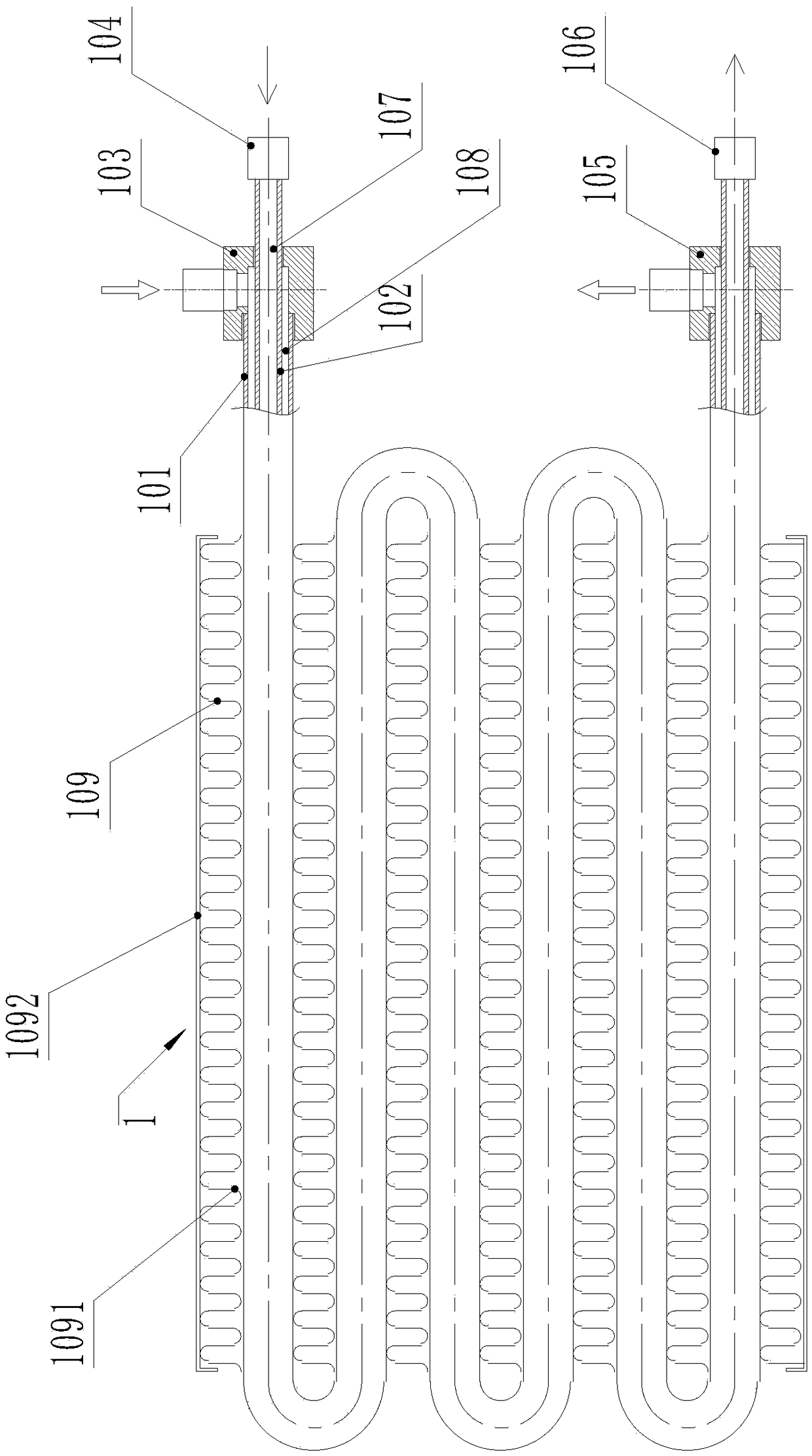
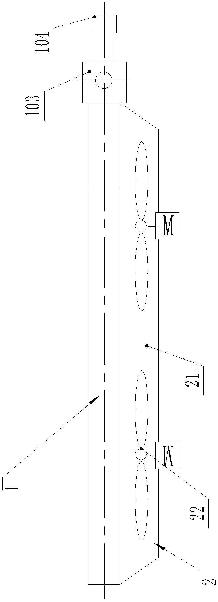
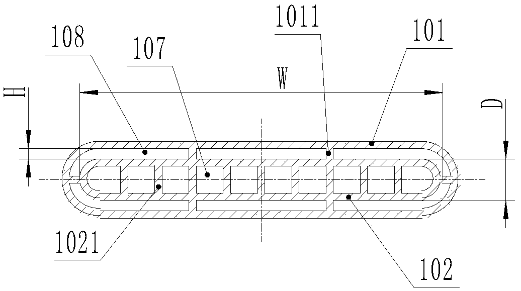
[0037] Such as Figure 1 to Figure 8 As shown, a water-cooled condenser for a new energy vehicle includes a condenser body 1 and a fan assembly 2. The condenser body 1 includes an outer tube 101 and an inner tube 102 that are mutually fitted and fixed, and the inner tube 102 is The cavity forms a refrigerant flow channel 107, and the space between the inner tube 102 and the outer tube 101 forms a water flow channel 108, and the refrigerant flow channel 107 and the water flow channel 108 are independent of each other.

[0038] The two ends of the outer pipe 101 are respectively provided with a water inlet joint 103 and the water outlet joint 105, and the two ends of the inner pipe 102 are respectively provided with a refrigerant inlet joint 104 and a refrigerant outlet joint 106, and the water inlet joint 103 and the water outlet joint 105 are connected with the water flow channel 108, the refrigerant inlet joint 104 and the refrigerant outlet joint 106 are both communicated wi...

Embodiment 2

[0050] Such as Figure 9 with Figure 10 As shown, the structure of this embodiment is basically the same as that of Embodiment 1, except that the structure of the condenser body 1 is changed. The inner tube 102 and the outer tube 101 in Embodiment 1 are formed into a coil structure, while this embodiment In the example, the number of inner tubes 102 and outer tubes 101 is multiple and all are straight tubes, the heat conducting fins 109 are arranged between adjacent straight tubes, the water inlet joint 103, the water outlet joint 105, the refrigerant The inlet joint 104 and the refrigerant outlet joint 106 are tubular structures and are respectively provided with a water inflow main channel, a water outflow main channel 1051, a refrigerant inflow main channel and a refrigerant outflow main channel. Figure 9 It can be seen from the figure that in the partial cross-sectional view of the water outlet joint 105, the water outlet joint 105 is a tubular structure, and the water ...


PUM


Abstract

The invention discloses a new energy automobile water-cooled condenser which comprises a condenser body and a draught fan assembly. The condenser body comprises an outer pipe and an inner pipe which are fixedly installed in a sleeve manner, a refrigerant flowing channel is formed in an inner cavity of the inner pipe, a water flowing channel is formed in a space between the inner pipe and the outerpipe, the two ends of the outer pipe are provided with a water inlet connector and a water outlet connector, the two ends of the inner pipe are provided with a refrigerant inlet connector and a refrigerant outlet connector, the water inlet connector and the water outlet connector both communicate with the water flowing channel, the refrigerant inlet connector and the refrigerant outlet connectorboth communicate with the refrigerant flowing channel, heat conduction fins are arranged outside the outer pipe, and the draught fan assembly is arranged on one side of the condenser body to be used for blowing air to or sucking air from the condenser body. By means of the water-cooled condenser, the inner pipe and the outer pipe which are installed in the sleeve manner are used for achieving heatexchange between medium water and a high temperature refrigerant, heat in the high temperature refrigerant is conveniently recovered, utilization of thermal energy in a new energy automobile is morereasonable, and the aim of energy saving is achieved.

Description

technical field [0001] The invention relates to a water-cooled condenser, in particular to a water-cooled condenser used in new energy vehicles. Background technique [0002] The condenser is a conventional device in the air-conditioning system. In the air-conditioning system of new energy vehicles, the main function of the condenser is to dissipate heat from the high-temperature refrigerant generated by the compressor after compression, so as to reduce the temperature of the refrigerant. Therefore, the working process of the condenser is an exothermic process. [0003] However, the current heat dissipation method of the condenser generally adopts air cooling, and the condenser includes a refrigerant flow pipeline for communicating with the outlet of the compressor. Fan, when the high-temperature refrigerant flows in the pipeline, the fan will air-cool the refrigerant, and the heat conduction fins can improve the air-cooling effect. [0004] However, the current condenser ...

Claims


Application Information

Patent Timeline
Patent Type & Authority Applications(China)
IPC IPC(8): F25B39/04F28F1/30
CPCF25B39/04F28F1/30F25B2339/047
Inventor 庹明慧
Owner 苏州赛普瑞新能源科技有限公司
Why Eureka
Try Eureka