Severe-convective cooling system for low-pressure continuous protective atmosphere heat treatment furnace

A technology of protective atmosphere and heat treatment furnace, which is applied in the field of strong convection cooling system, can solve the problems of increased manufacturing cost, difficult control of gas flow in the cooling chamber, and low cooling efficiency, so as to improve cooling efficiency and production efficiency, ensure heat treatment effect, improve The effect of cooling efficiency

Active Publication Date: 2010-01-06
SUZHOU ZHONGMENZI TECH
View PDF7 Cites 0 Cited by
  • Summary
  • Abstract
  • Description
  • Claims
  • Application Information

AI Technical Summary

Problems solved by technology

Due to the low cooling efficiency of this method, usually a protective atmosphere furnace needs to be installed with many levels of water cooling chambers, which not only increases the manufacturing cost, but also occupies a large area during installation, and also makes it very troublesome for technicians to manage
In order to speed up the cooling speed, there is also a circulation fan used in a low furnace pressure continuous protective atmosphere heat treatment furnace to carry out a strong convection cooling system for circulating cooling, but it is found during use that due to the existence of strong convection, the gas flow in the cooling chamber is difficult to control, and It is easy to generate turbulent flow, and local area generates vacuum negative pressure, which makes the external air or the protective gas of adjacent parts flow back into the cooling chamber, thus affecting the heat treatment effect of the workpiece

Method used


Image

  • Severe-convective cooling system for low-pressure continuous protective atmosphere heat treatment furnace
  • Severe-convective cooling system for low-pressure continuous protective atmosphere heat treatment furnace
  • Severe-convective cooling system for low-pressure continuous protective atmosphere heat treatment furnace

Examples


Embodiment Construction

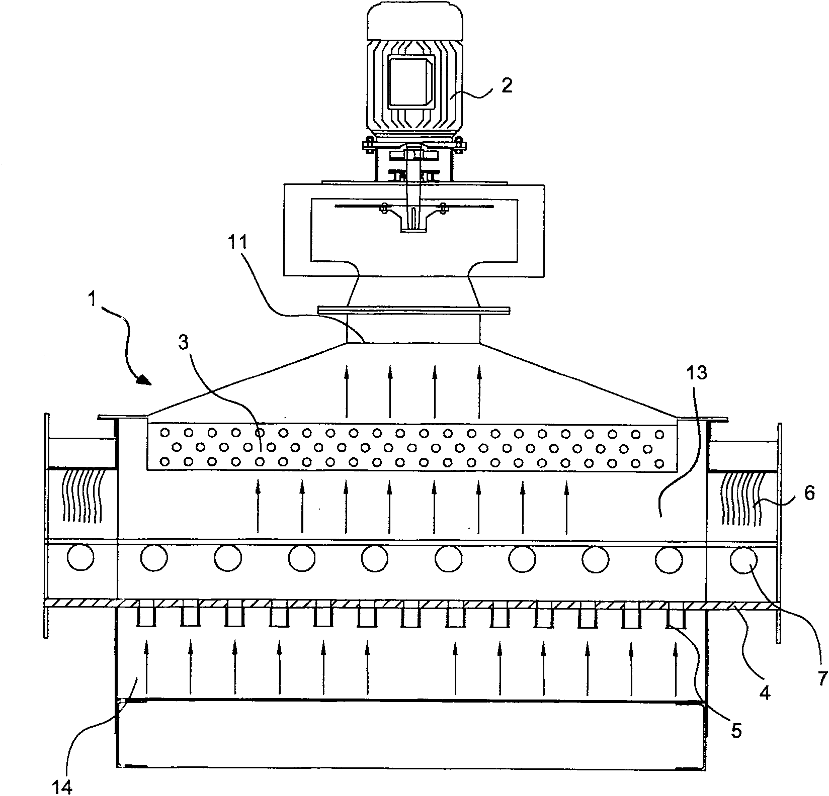
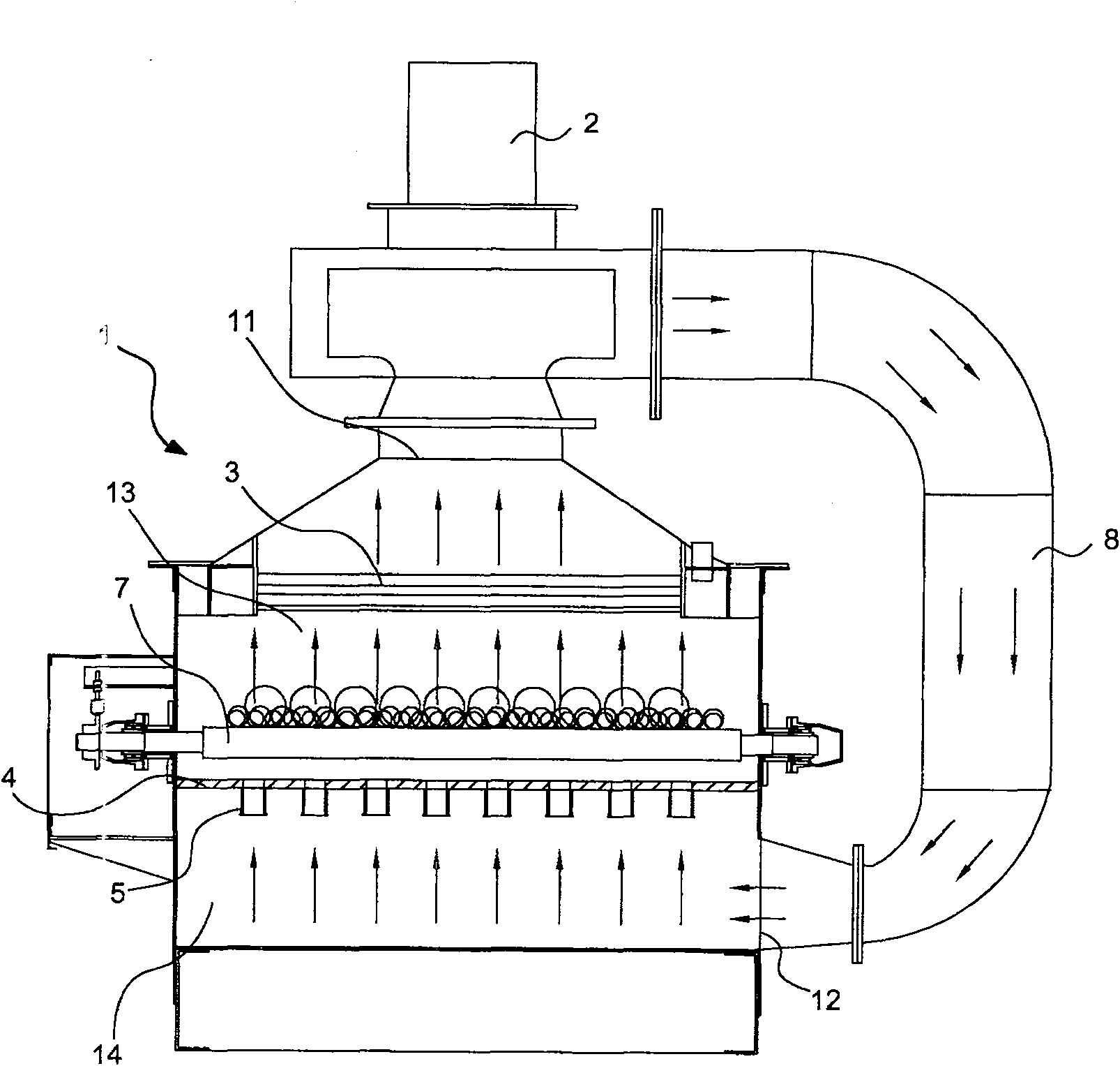
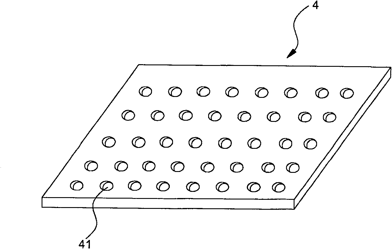
[0017] See attached Figure 1~2 The strong convection cooling system shown includes a cooling chamber 1 with a workpiece rack 7 inside, a strong convection circulating fan 2, a heat exchanger 3, and a circulating air duct 8. The top and bottom of the cooling chamber 1 are respectively provided with return air outlets 11 and The air supply port 12 and the air return port 11 communicate with the air inlet of the strong convection circulating fan 2 , and the air supply port 12 communicates with the air outlet of the circulating fan 2 through the circulating air channel 8 . Also be provided with dividing plate 4 (structure such as image 3 shown), a plurality of hollow draft tubes 5. The partition plate 4 is located below the workpiece frame 7 and divides the cooling chamber 1 into two parts, the upper chamber 13 and the lower chamber 14. The partition plate 4 is provided with several holes 41, and a plurality of hollow guide tubes 5 are corresponding to each other. Installed at...


PUM


Abstract

The invention relates to a strong convection cooling system of a continuous passing protective atmosphere annealing oven with low furnace pressure, which comprises a cooling chamber with a built-in work rest, a strong convection circulating fan, a heat-cold exchanger and a circulating air channel, wherein an air return is arranged on the top portion of the cooling chamber, an air supply outlet is arranged on the bottom of the cooling chamber, the air return is communicated with the air inlet of the circulating fan, the air supply outlet is communicated with the air outlet of the strong convection circulating fan through the circulating air channel, a baffle is arranged in the cooling chamber, the baffle which is located on the low portion of the work rest separates the cooling chamber into an upper cavity chamber and a lower cavity chamber, a plurality of diversion channels are arranged on the baffle, the upper cavity chamber and the lower cavity chamber are communicated through the diversion channels, air flow forms laminar flow when air flow flows into the upper cavity chamber after flowing through the diversion channels, protective air flow enters into the cooling chamber through the air supply outlet, and is sprayed on the surface of a work-piece in the laminar flow way after flowing through an air flow channel, thereby achieving the purpose of evenly cooling the work-piece, and largely increasing the cooling effect.

Description

technical field [0001] The invention relates to a strong convection cooling system of a heat treatment furnace. The system is applied to various protective atmosphere furnaces in the heat treatment process, especially for the cooling section of the low furnace pressure continuous protective atmosphere heat treatment furnace. Background technique [0002] In the cooling system of the existing low furnace pressure continuous protective atmosphere heat treatment furnace, the multi-stage water cooling method is used to cool the workpiece. The commonly used water cooling method includes setting a water cooling jacket in the cooling chamber, and using the circulating water in the water cooling jacket for radiation and conduction cooling. . Due to the low cooling efficiency of this method, usually a protective atmosphere furnace needs to be installed with many levels of water cooling chambers, which not only increases the manufacturing cost, but also occupies a large area during in...

Claims


Application Information

Patent Timeline
Patent Type & Authority Patents(China)
IPC IPC(8): C21D1/74F27D9/00
Inventor 蒋明根
Owner SUZHOU ZHONGMENZI TECH
Why Eureka
Try Eureka