

Piping
A technology for piping and main piping, applied in the direction of pipes, pipe elements, rigid pipes, etc., can solve problems such as insufficient cavitation flow control, piping thermal fatigue, and adverse effects of piping, so as to prevent adverse effects, prevent thermal fatigue, and suppress intrusive effect
- Summary
- Abstract
- Description
- Claims
- Application Information
AI Technical Summary
Problems solved by technology
Method used
Image

Examples
no. 1 approach
[0067] Below, refer to figure 1 and figure 2 The branch tube of the first embodiment of the present invention will be described.
[0068] figure 1 It is a schematic diagram explaining the branch pipe structure of this embodiment.
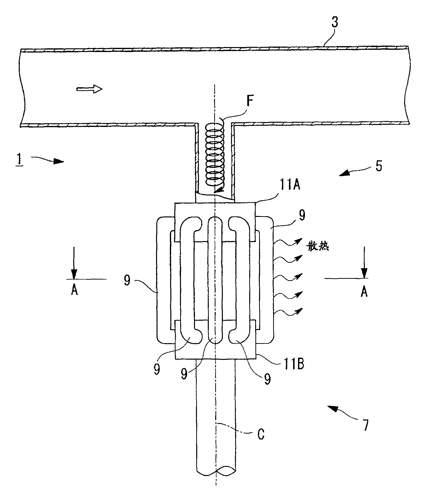
[0069] Such as figure 1 As shown, a branch pipe (pipe) 1 is a pipe branched from a main pipe 3 through which high-temperature water flows.
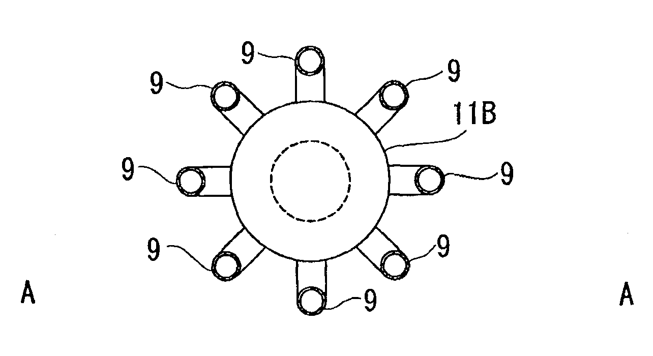
[0070] The branch pipe 1 has: a first pipe (distribution mechanism) 5 connected to the main pipe 3; a second pipe (distribution mechanism) 7 separated from the first pipe 5; The pipe is the connecting pipe (distribution mechanism) 9 .
[0071] The side of the first piping 5 and the second piping 7 ( figure 1 The end portion on the lower side) forms a connecting portion 11A having a diameter larger than that of other portions. The connection pipe 9 is connected to the peripheral surface of the connection portion 11A. The second piping 7, the first piping 5 side ( figure 1 The end portion on the upper s...
no. 2 approach
[0085] Next, refer to image 3 A second embodiment of the present invention will be described.
[0086] image 3 It is a schematic diagram explaining the branch pipe structure of this embodiment.
[0087] Components that are the same as in the first embodiment are denoted by the same reference numerals, and description thereof will be omitted.
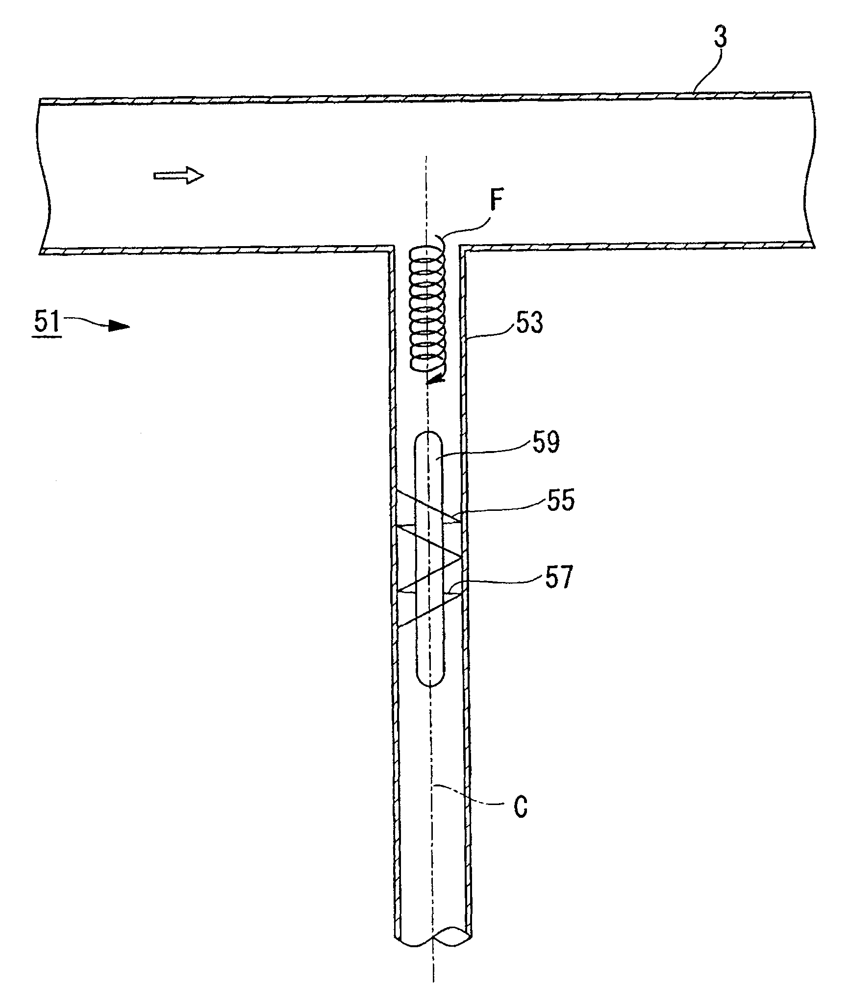
[0088] Such as image 3 As shown, the branch pipe (pipe) 51 is a pipe branched from the main pipe 3 through which high-temperature water flows.
[0089] The branch pipe 51 has: a pipe 53 connected to the main pipe 3; a first rotating blade (first screw member, obstructing mechanism) 55 and a second rotating blade (second spiral member, obstructing mechanism) 57 arranged in the pipe 53; The support portion 59 supports the first and second rotary blades 55 and 57 .
[0090] The first rotary blade 55 is a helical blade that rotates in one rotation direction (for example, a clockwise rotation direction away from the main pipe 3 ). Th...
no. 3 approach
[0099] Next, refer to Figure 4 A third embodiment of the present invention will be described.
[0100] Figure 4It is a schematic diagram explaining the branch pipe structure of this embodiment.
[0101] Components that are the same as in the first embodiment are denoted by the same reference numerals, and description thereof will be omitted.
[0102] Such as Figure 4 As shown, the branch pipe (pipe) 101 is a pipe branched from the main pipe 3 through which high-temperature water flows.
[0103] The branch pipe 101 has a pipe 103 connected to the main pipe 3 , and a labyrinth structure part (flow path blocking part, obstructing mechanism) 105 arranged in the pipe 53 .
[0104] The labyrinth structure portion 105 has a plurality of plate members 107 extending radially inward from the inner wall of the pipe 103 . The plurality of plate members 107 block a part of the flow path in the piping 103 and allow water to flow through the remaining openings 109 .
[0105] In addi...
PUM
 Abstract
Description
Claims
Application Information