Green energy-saving electric arc furnace control device
A control device and electric arc furnace technology, which is applied in electric controllers, electrical program control, program control in sequence/logic controllers, etc., can solve problems such as low production efficiency, large unit consumption, and large influence on the power grid, and achieve production Efficiency improvement, consumption reduction, and the effect of reducing the number of trips
- Summary
- Abstract
- Description
- Claims
- Application Information
AI Technical Summary
Problems solved by technology
Method used
Image
Examples
Embodiment 1
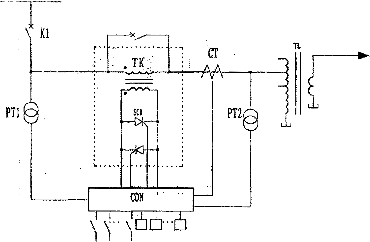
[0012] Embodiment 1 is suitable for low-power electric arc furnace control, such as figure 1 As shown, the starting end of the primary winding of the switching transformer TK is connected to the power supply through the circuit breaker K1, and the end is connected to the corresponding tap of the electric arc furnace transformer TL; the two ends of the secondary winding of the switching transformer are connected with positive and negative parallel thyristors SCR; And the phase control triggering unit circuit is realized by the single-chip microcomputer system CON, its signal input terminal is connected with current transformer CT, voltage transformer PT1, PT2, and the output terminal is connected with the control terminal of the thyristor.
Embodiment 2
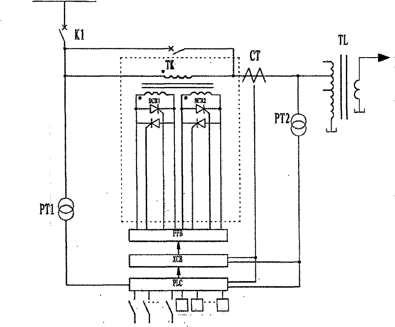
[0013] Embodiment 2 is suitable for medium power electric arc furnace control, such as figure 2 As shown, the difference from Embodiment 1 is that in this embodiment, two secondary windings are provided for each phase of the switching transformer, and the secondary windings are independent. The unit circuit adopts a programmable controller PLC, and the phase control trigger unit circuit adopts a phase control trigger board XCB composed of an integrated circuit. The signal output terminal of the phase control trigger board XCB is connected to the amplifying circuit FFB, and the signal output terminal of the amplifying circuit is connected to the control terminal of the thyristor; The given input terminal of the control trigger board XCB is connected to the main control unit circuit, and the signal input terminals of the phase control trigger board XCB and the main control unit circuit are connected to the current transformer CT, voltage transformer PT1, PT2.
Embodiment 3
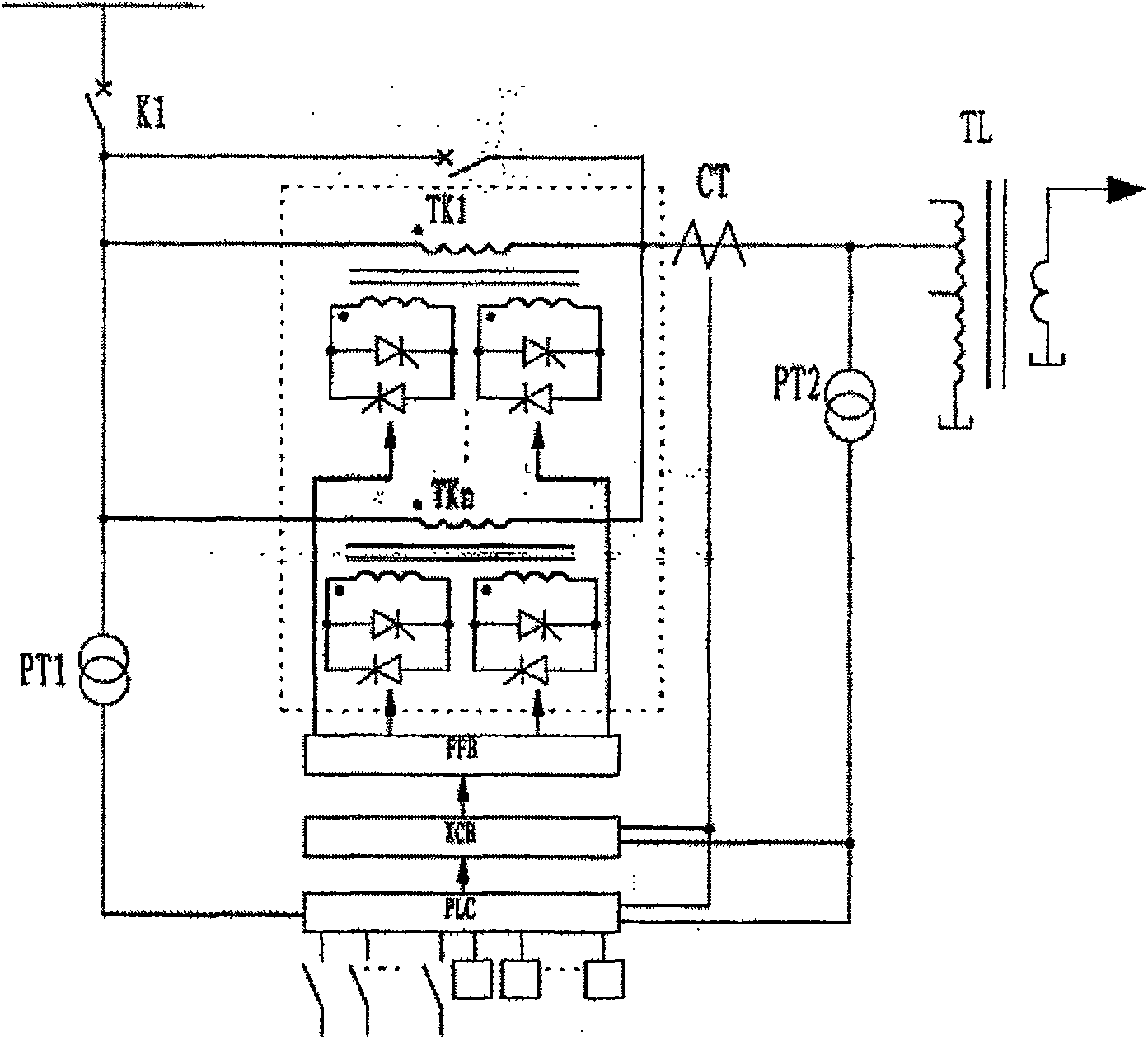
[0014] Embodiment 3 is suitable for high-power electric arc furnace control, such as image 3 As shown, the difference from Embodiment 2 is that there are multiple switching transformers TK1-TKn, and the primary windings of each transformer are connected to the same end, one end is connected to the power supply through the circuit breaker, and the other end is connected to the corresponding tap of the electric arc furnace transformer. The windings are independent, and the two ends of the secondary winding are connected with positive and negative parallel thyristors accordingly. The role of parallel connection of multiple switching transformers is to increase the control power. In principle, it is equivalent to parallel connection of multiple thyristors in the same direction through the leakage reactance of switching transformers. The current sharing effect is better, and the current of each channel is basically the same.
[0015] The role of the switching transformer TK in the...
PUM
 Abstract
Description
Claims
Application Information
 - R&D
- Intellectual Property
- Life Sciences
- Materials
- Tech Scout
- Unparalleled Data Quality
- Higher Quality Content
- 60% Fewer Hallucinations
Browse by: Latest US Patents, China's latest patents, Technical Efficacy Thesaurus, Application Domain, Technology Topic, Popular Technical Reports.
© 2025 PatSnap. All rights reserved.Legal|Privacy policy|Modern Slavery Act Transparency Statement|Sitemap|About US| Contact US: help@patsnap.com


