Pipe end spinning, rolling-out and flange turning machine

A technology of flanging machine and pipe end, which is applied in the field of pipe end spinning and flaring flanging machine, which can solve the problems of many processing steps, many processing procedures, poor finish, etc.

Inactive Publication Date: 2010-02-10
CHINA NAT OFFSHORE OIL CORP +3
View PDF6 Cites 0 Cited by
  • Summary
  • Abstract
  • Description
  • Claims
  • Application Information

AI Technical Summary

Problems solved by technology

Stamping (cold heading) and rolling methods, the equipment has high power, high energy consumption, and is bulky, and the finish of the flanging is poor; the spinning method is the first choice because of its low energy consumption, compact equipment, and high processing quality
However, spinning flaring and flanging needs special equipment to complete, and there are many processing procedures, many processing steps, and there are many manual steps.

Method used


Image

  • Pipe end spinning, rolling-out and flange turning machine
  • Pipe end spinning, rolling-out and flange turning machine
  • Pipe end spinning, rolling-out and flange turning machine

Examples


Embodiment 1

[0041] Embodiment 1: Flaring and flanging are performed on the pipe end with a pipe diameter of 60 mm to form a 37-degree flanging. Install clamping jaws matching the outer diameter of the pipe to be processed on the clamping mechanism, send the pipe to be processed into the clamping mechanism, open the clamping oil cylinder, clamp and clamp the pipe, and reserve a flanging straight edge (Such as Figure 4a shown); then install the spinning head on the propelling body, the specification of the spinning head is that the cone angle is 30 degrees, and the height is 100mm, and the jacking cylinder and hydraulic motor are turned on to carry out the jacking and spinning work (such as Figure 4b shown), so that the propelling body drives the spinning head to contact the reserved flanging straight edge of the pipe body, through the control valve group of the hydraulic mechanism, the jacking thrust is controlled to 25kN (kilonewton), and the spinning torque is 290N-m (N-m ), until the...

Embodiment 2

[0042] Embodiment 2: Flaring and flanging are performed on the end of a pipe with a pipe diameter of 168 mm to form a 37-degree flanging. Install clamping jaws matching the outer diameter of the pipe to be processed on the clamping mechanism, send the pipe to be processed into the clamping mechanism, open the clamping oil cylinder, clamp and clamp the pipe, and reserve a flanging straight edge (Such as Figure 5a shown); then install the spinning head on the propelling body, the specification of the spinning head is 30° at the tip angle of the cone, and the height is 160mm, and the jacking cylinder and hydraulic motor are turned on to carry out the pushing and spinning work (such as Figure 5b shown), so that the propelling body drives the spinning head to contact the reserved flanging straight edge of the pipe body, through the control valve group of the hydraulic mechanism, the jacking thrust is controlled to 25kN (kilonewton), and the spinning torque is 290N-m (N-m ), unti...

Embodiment 3

[0043] Embodiment 3: Flaring and flanging the pipe end with a pipe diameter of 168 mm, forming a 90-degree flanging (as shown in FIG. 6 ). Send the pipe fittings to be processed into the clamping mechanism, open the clamping oil cylinder, clamp and clamp the pipe fittings, and reserve a straight edge for flanging, and first flang the pipe end at 37 degrees, as described in the first operation example; On the basis of completing the flanging at 37 degrees, replace the spinning head with a cone angle of 130 degrees and a height of about 140 mm to flang the pipe body at 37 degrees to 90 degrees. The operation process is as described in Example 1; The control valve group of the mechanism controls the jacking force to 25kN (kilonewton), and the spinning torque to 290N-m (N-m), until the end of the pipe body forms a 90-degree flanging, and then stops.


PUM

PropertyMeasurementUnit
angleaaaaaaaaaa
lengthaaaaaaaaaa
voltage ratingaaaaaaaaaa

Abstract

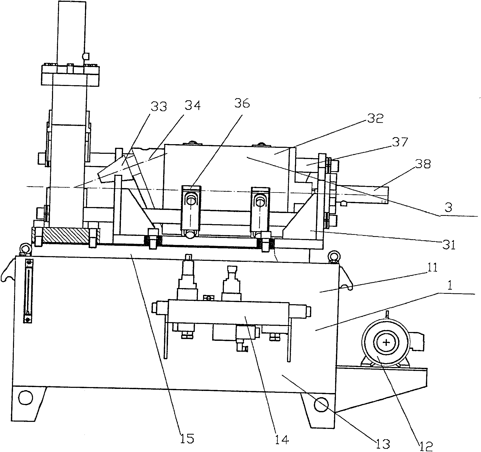
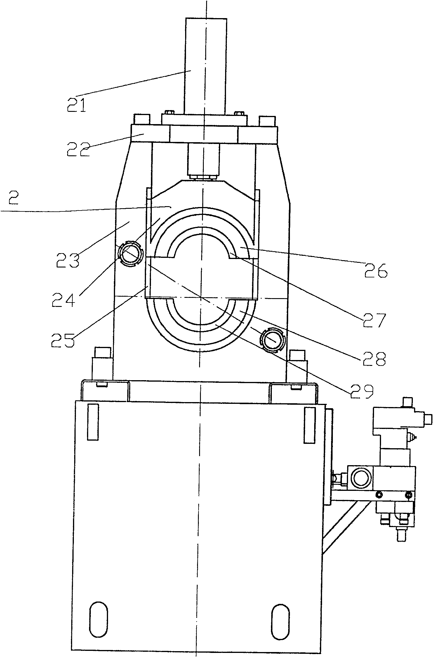
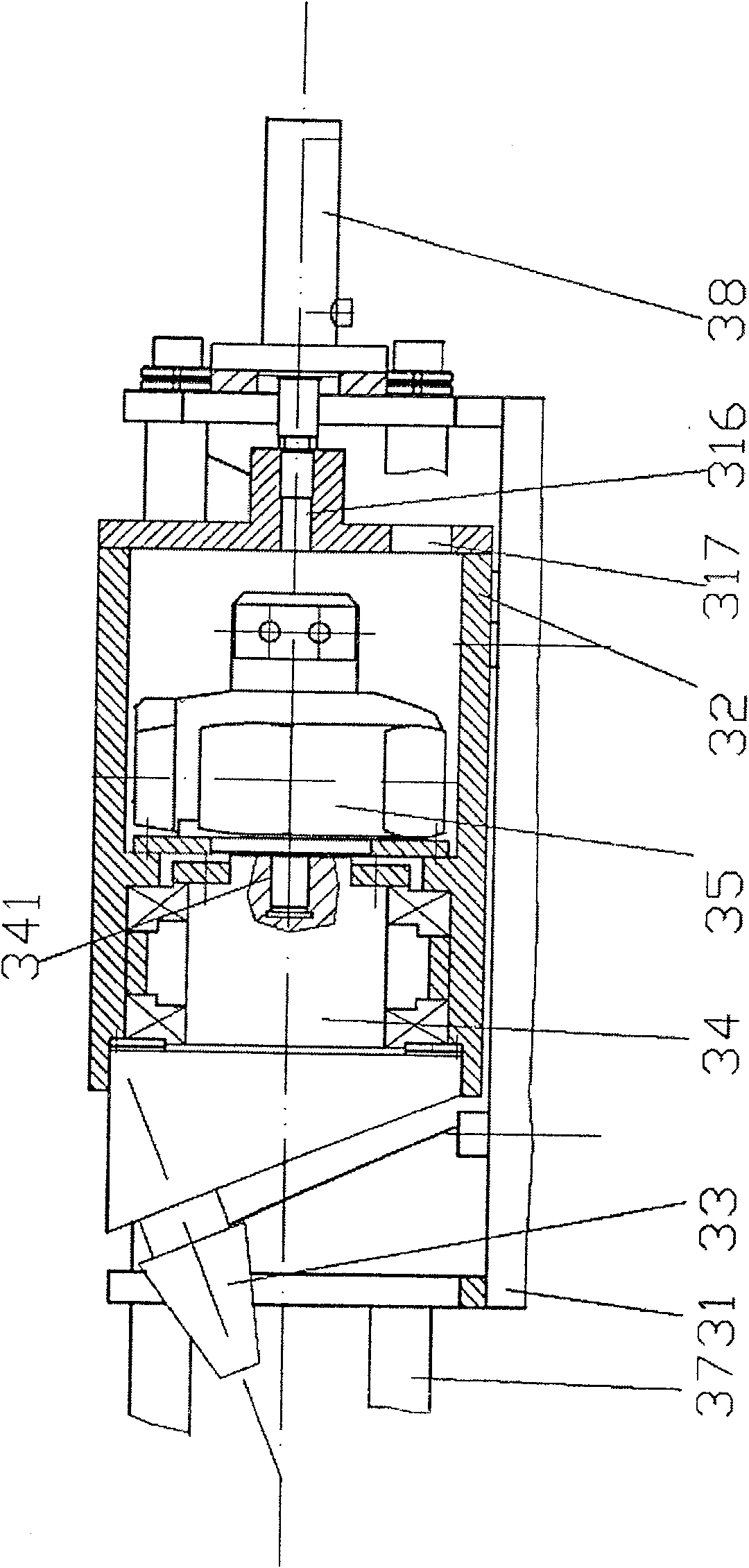
The invention discloses a rotary-pressing flaring flanger at a tube end. A hydraulic mechanism comprises a motor--oil pump, an oil box and a control valve set; the oil pump and the control valve set are connected with the oil box; the control valve set is fixed on the body of the oil box and is connected with the oil cylinder of a clamping mechanism, the hydraulic motor of a rotary-press mechanismand a jacking oil cylinder; the frame of the clamping mechanism is fixed on the panel of the oil box of the hydraulic mechanism; an upper crossbeam fixes the oil cylinder; the piston rod of the oil cylinder is connected with a slide block; a lead rail fixed by the frame is internally provided with the slide block which is connected with the piston rod of the oil cylinder and fixes an upper module; the upper module is provided with an upper clamping jaw; a lower module is fixed on the frame and is provided with a lower clamping jaw; the frame of the rotary-press mechanism is fixed on the panelof the oil box of the hydraulic mechanism; one end of two guide shafts is respectively fixed with the frame of the clamping mechanism and the other ends are fixed at the other side wall of the frame;a shell is provided with a slide bearing and is fixed at the two guide shafts; a pushing body provided with a rotary-press head and a hydraulic motor are arranged in the shell; the pushing body is connected with the output shaft of the hydraulic motor; the jacking oil cylinder is fixed on the frame and the piston rod of the jacking oil cylinder is connected with the shell; the rotary-pressing flaring flanger is suitable for the flaring flanging process of various calibers at the tube end.

Description

technical field [0001] The invention relates to pipeline processing equipment, in particular to a pipe end spinning and flaring flanging machine used for pipeline end connection processing. Background technique [0002] In the field of petroleum and chemical industry, and in the field of ship hydraulic system, a large number of pipelines need to be built, and the pipelines are generally composed of pipes of different lengths connected. At present, the connection methods of pipelines are mainly welded connection and flange connection, both of which are inseparable from the girth welding of the pipe end, which will inevitably bring about the shortcomings of the welding process itself, such as the low efficiency of arc welding with electrodes , Poor working conditions, etc. Now a method of connecting pipelines with special flanges and sealing devices has been developed abroad. Although the special flanges and seals are produced on a large scale to ensure high efficiency and hi...

Claims


Application Information

Patent Timeline
Patent Type & Authority Patents(China)
IPC IPC(8): B21D41/02B21D19/02B21D22/14
Inventor 王国栋虞明星白秉仁红鹰肖聚亮胡晓明王东锋王刚
Owner CHINA NAT OFFSHORE OIL CORP
Why Eureka
Try Eureka