Adjustable cantalever type dynamic pressure gas elastic foil bearing
An elastic foil and cantilever type technology, applied in the field of dynamic pressure gas elastic foil bearings, can solve the problems of low bearing capacity, bearing lubrication gas end leakage, poor bearing stability, etc., to improve bearing capacity, reduce leakage, The effect of increasing the equivalent stiffness
- Summary
- Abstract
- Description
- Claims
- Application Information
AI Technical Summary
Problems solved by technology
Method used
Image
Examples
specific Embodiment approach 1
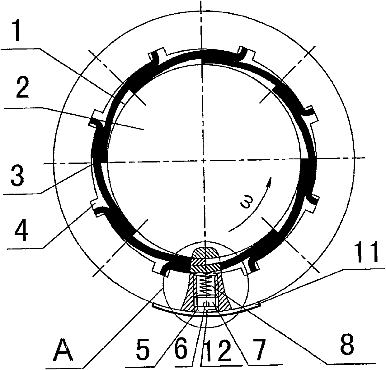
[0008] Specific implementation mode one: as figure 1 As shown, the adjustable cantilever type dynamic pressure gas elastic foil bearing of this embodiment is composed of a bearing housing 1, an elastic foil 3, and an adjustable mechanism 9; the elastic foil 3 is installed in the bearing housing 1 The walls are evenly arranged along the inner wall of the bearing housing 1, one end of the elastic foil 3 is fixedly installed in the longitudinal groove 4 provided on the inner wall of the bearing housing 1, and the other end of the elastic foil 3 overlaps the adjacent On the elastic foil; the adjustable mechanism 9 is installed in the internal threaded through hole 5 of the housing 1 and screwed with the threaded through hole 5 , the adjustable mechanism 9 is in contact with the elastic foil 3 . During use, journal 2 is contained on the bearing.
specific Embodiment approach 2
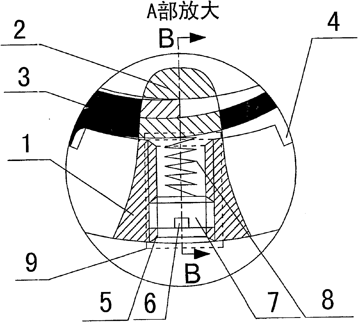
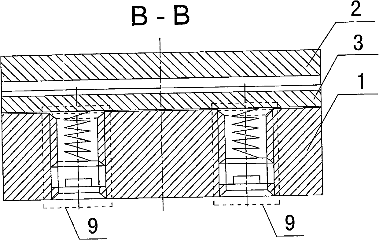
[0009] Specific implementation mode two: as figure 2 As shown, the adjustable mechanism 9 described in this embodiment is composed of a cylindrical plug 7 and a cylindrical spring 8, the inner end of the cylindrical plug 7 is in contact with the outer end of the cylindrical spring 8, and the outer end surface of the cylindrical plug 7 is provided with a Square groove 6 is arranged, and square groove 6 facilitates the adjustment of the in and out of cylinder plug 7. This structure is simple and easy to process. Other components and connections are the same as those in the first embodiment.
specific Embodiment approach 3
[0010] Specific embodiment three: the adjustable mechanism 9 described in this embodiment is composed of a cylindrical long wire plug 10, a thin steel wire rod 13 and a cylindrical spring 8, the inner end of the cylindrical long wire plug 10 is in contact with the outer end of the cylindrical spring 8, The cylindrical long screw plug 10 is radially provided with a first locking through hole 10-1 and a second locking through hole 10-2 perpendicular to each other, and a thin steel wire rod 13 is inserted into the radial first locking hole. In the tight through hole 10 - 1 or the second locked through hole 10 - 2 , a first square groove 14 is provided on the outer end surface of the cylindrical long thread plug 10 . This structure can effectively adjust the compression amount of the cylindrical spring 8 and has a first locking through hole 10-1 and a second locking through hole 10-2. The structure is simple and compact, and the locking effect is good. Other components and connect...
PUM
 Abstract
Description
Claims
Application Information
 - R&D
- Intellectual Property
- Life Sciences
- Materials
- Tech Scout
- Unparalleled Data Quality
- Higher Quality Content
- 60% Fewer Hallucinations
Browse by: Latest US Patents, China's latest patents, Technical Efficacy Thesaurus, Application Domain, Technology Topic, Popular Technical Reports.
© 2025 PatSnap. All rights reserved.Legal|Privacy policy|Modern Slavery Act Transparency Statement|Sitemap|About US| Contact US: help@patsnap.com


