Connection structure between batteries

A connection structure and electrical connection technology, which is applied in the direction of conductive connection, structural parts, battery box/coating, etc., can solve the problems of high manufacturing cost, increased weight of connecting parts, expensive battery modules or battery packs, etc., to achieve manufacturing Easy process, sufficient heat dissipation effect, and simplified structure

Inactive Publication Date: 2010-02-17
PANASONIC CORP
View PDF4 Cites 2 Cited by
  • Summary
  • Abstract
  • Description
  • Claims
  • Application Information

AI Technical Summary

Problems solved by technology

[0010] As described above, in the conventional inter-battery connection structure, two types of connecting members of different shapes corresponding to the series arrangement in the battery axis direction and the parallel arrangement in the radial direction are required, so when configuring a battery module or a battery pack In this case, two types of connecting parts are required, and the cost of parts including metal molds increases accordingly, and the manufacturing cost becomes higher, so the manufactured battery module or battery pack becomes expensive.
In addition, in any connection structure between batteries, two adjacent batteries are connected by welding of connecting members. Therefore, when some batteries are found to be consumed or deteriorated during maintenance of the battery module, it is necessary to Replacing the battery module as a whole will increase the operating cost
[0011] Therefore, it is expected that a large cylindrical battery such as a nickel metal hydride battery with a large capacity of about 100Ah and a weight of about 1.6Kg will be put into practical use in the near future. Figure 8 or Figure 9 When such a large cylindrical battery is formed into a battery module or a battery pack, the structure of the connection structure between these batteries is relatively complicated, and the welding process becomes difficult along with it, and the weight of the connecting parts increase, and it is difficult to ensure sufficient strength when impacted, so it is expected that it will be difficult to put it into practical use

Method used


Image

  • Connection structure between batteries
  • Connection structure between batteries
  • Connection structure between batteries

Examples


Embodiment Construction

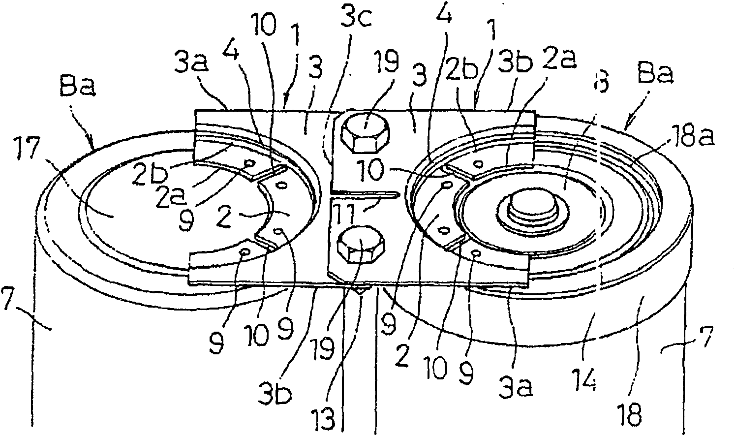
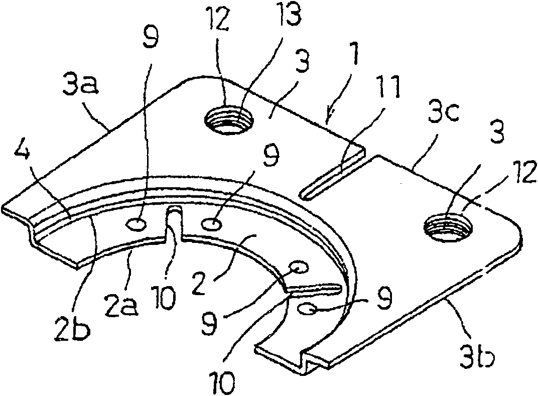
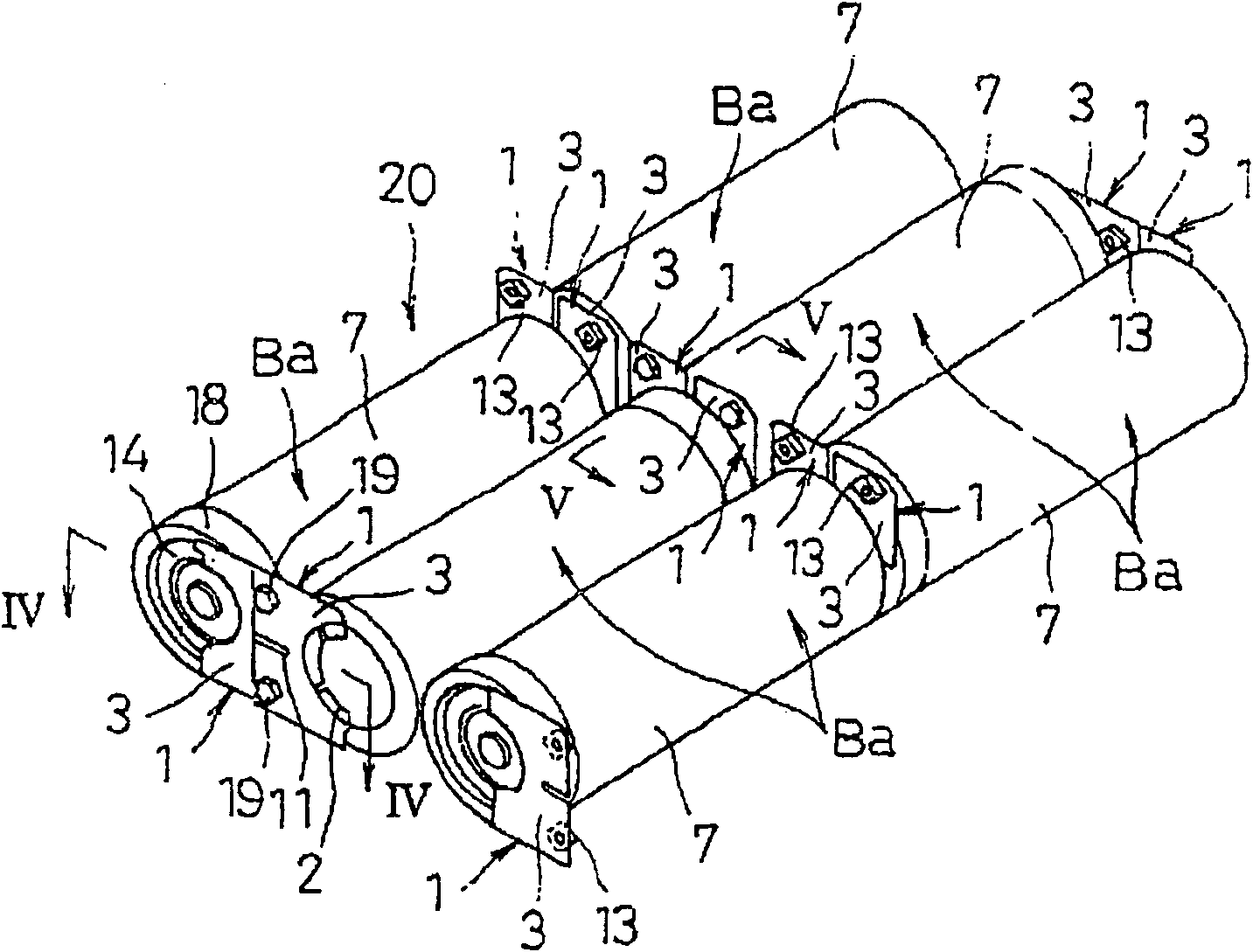
[0039] Hereinafter, preferred embodiments of the present invention will be described with reference to the drawings. figure 1 It is a perspective view showing the connection structure of the inter-battery connection structure according to one embodiment of the present invention, figure 2 It is a perspective view showing the inter-battery connection plate 1 used for this connection. first of all, yes figure 2 The inter-battery connecting plate 1 will be described. This inter-battery connection plate 1 has a shape that integrally connects the welding portion 2 fixed to the battery case 7 by welding means and the connecting portion 3 extending from the welding portion 2 via a step portion 4, and the welding portion 2 is relatively connected to the connecting plate 1. Part 3 is a recess.

[0040] The above soldered part 2 has to be included in the figure 1 The shown battery Ba has a semicircular shape in the circular end surface of the battery case 7 . Specifically, it ha...


PUM


Abstract

An inter-cell connecting plate (1) having integrally a welding portion (2) to be included in the circular end surface of a cell case (7) and a connection portion (3) extending from the welding portion(2) is provided, welding portions (2) are respectively welded to one electrode terminal of the cell case (7) and the other electrode terminal to fix inter-cell connecting plates (1), and respective connection portions (3) of inter-cell connecting plates (1) respectively fixed to two adjoining cylindrical cells (Ba) are overlapped each other and linked in a electrically connected state, thereby making it possible to connect two adjoining cells together by the same inter-cell connecting plate (1) when a plurality of cylindrical cells (Ba) are disposed either in series axially or in parallel radially, whereby costs can be reduced, sufficient radiation effect is achieved, and sufficient robustness and weight reduction can be ensured even a large cylindrical cells are connected.

Description

technical field [0001] The present invention relates to an inter-battery connection structure for constituting a battery module or a battery pack mainly by connecting a plurality of cylindrical batteries in series or in parallel to obtain a desired output voltage. Background technique [0002] In recent years, the portability and wirelessization of electronic equipment such as AV equipment, personal computers, and portable communication equipment have developed rapidly. As the driving power supply for these electrical equipment, nickel-cadmium batteries or nickel-metal hydride batteries are used because of their high reliability and easy maintenance. , lithium secondary batteries, etc. On the other hand, lead storage batteries are currently the mainstream in applications such as back-up emergency power supplies in the event of power outages caused by disasters such as earthquakes and typhoons, but in the future it is expected to use nickel metal hydride storage batteries wit...

Claims


Application Information

Patent Timeline
Patent Type & Authority Patents(China)
IPC IPC(8): H01M2/20H01M2/10H01M50/529H01M50/503H01M50/51H01M50/516H01M50/517H01M50/522H01M50/526
CPCH01M2/022H01M2/204H01M6/42H01M50/107H01M50/522H01M50/526H01M50/516H01M50/517H01M50/51H01M50/503H01M50/50H01M50/20
Inventor 福冈孝博加藤正彦
Owner PANASONIC CORP
Why Eureka
Try Eureka