Control system for signal wire width and method thereof

A width control and signal line technology, applied in the field of signal line width control, can solve the problems of taking a long time, prolonging the wiring cycle, and affecting the quality of wiring, etc., and achieve the effect of overcoming complicated operation steps, improving work efficiency, and saving working time

Inactive Publication Date: 2010-02-24
INVENTEC CORP
View PDF6 Cites 1 Cited by
  • Summary
  • Abstract
  • Description
  • Claims
  • Application Information

AI Technical Summary

Problems solved by technology

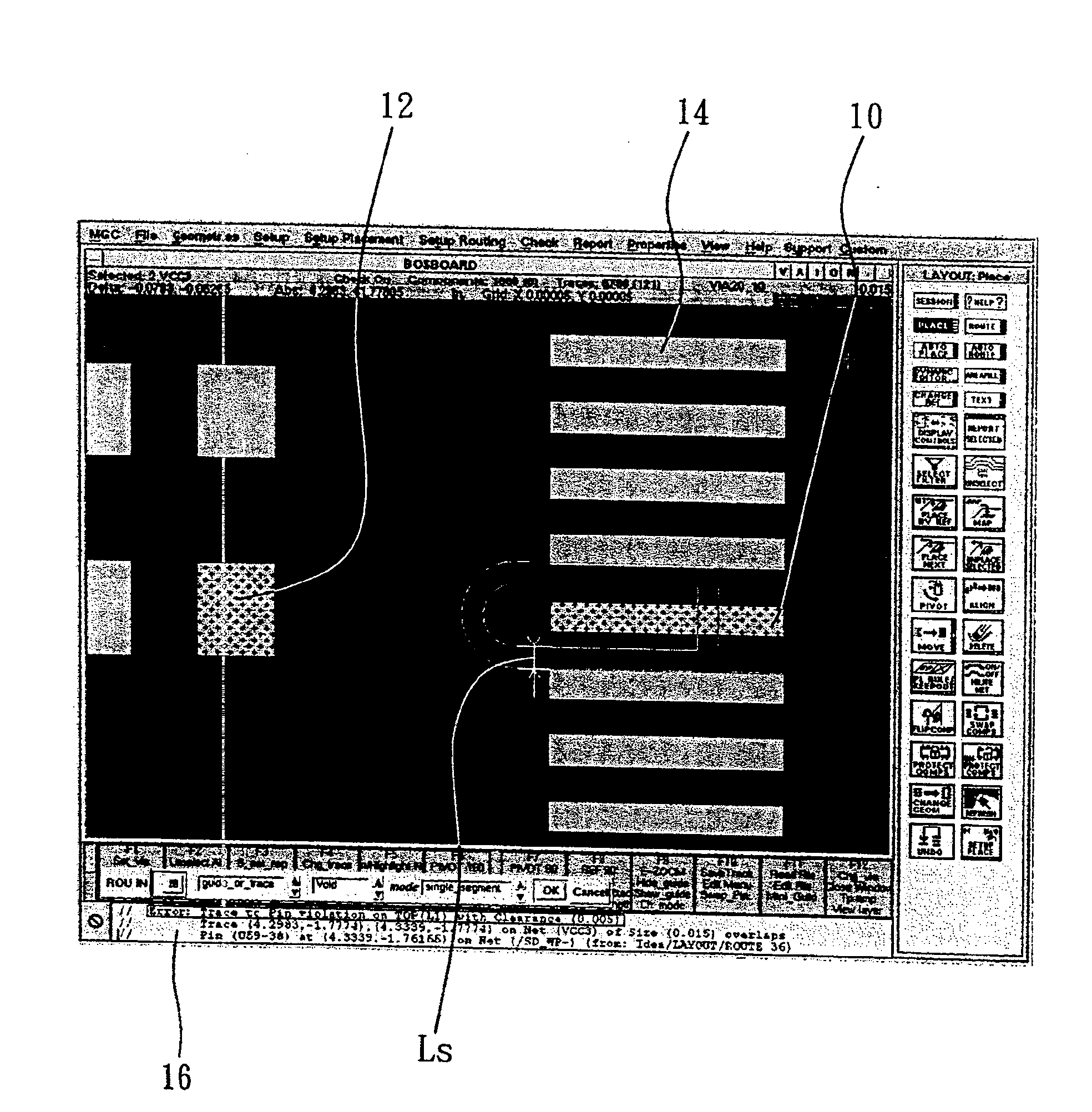
[0005] It can be seen from the above that in the existing wiring software, the wiring personnel need to go through multiple setting steps before entering the line width in the dialog box for inputting the line width, that is, the part pin width, and then need to go through the same operation Modifying the line width makes the operation steps cumbersome, and because the wiring personnel cannot effectively and instantly know the pin width information of the part, the wiring personnel need to spend a long time in the dialog box for multiple setting inputs to determine the effective line width, causing the wiring personnel The work efficiency is reduced, the wiring cycle is prolonged, and in severe cases, the wiring quality is even more affected

Method used


Image

  • Control system for signal wire width and method thereof
  • Control system for signal wire width and method thereof
  • Control system for signal wire width and method thereof

Examples


Embodiment Construction

[0035] Embodiments of the present invention are described below through specific examples, and those skilled in the art can easily understand other advantages and effects of the present invention from the content disclosed in this specification. The present invention can also be implemented or applied through other different specific embodiments, and various modifications and changes can be made to the details in this specification based on different viewpoints and applications without departing from the spirit of the present invention.

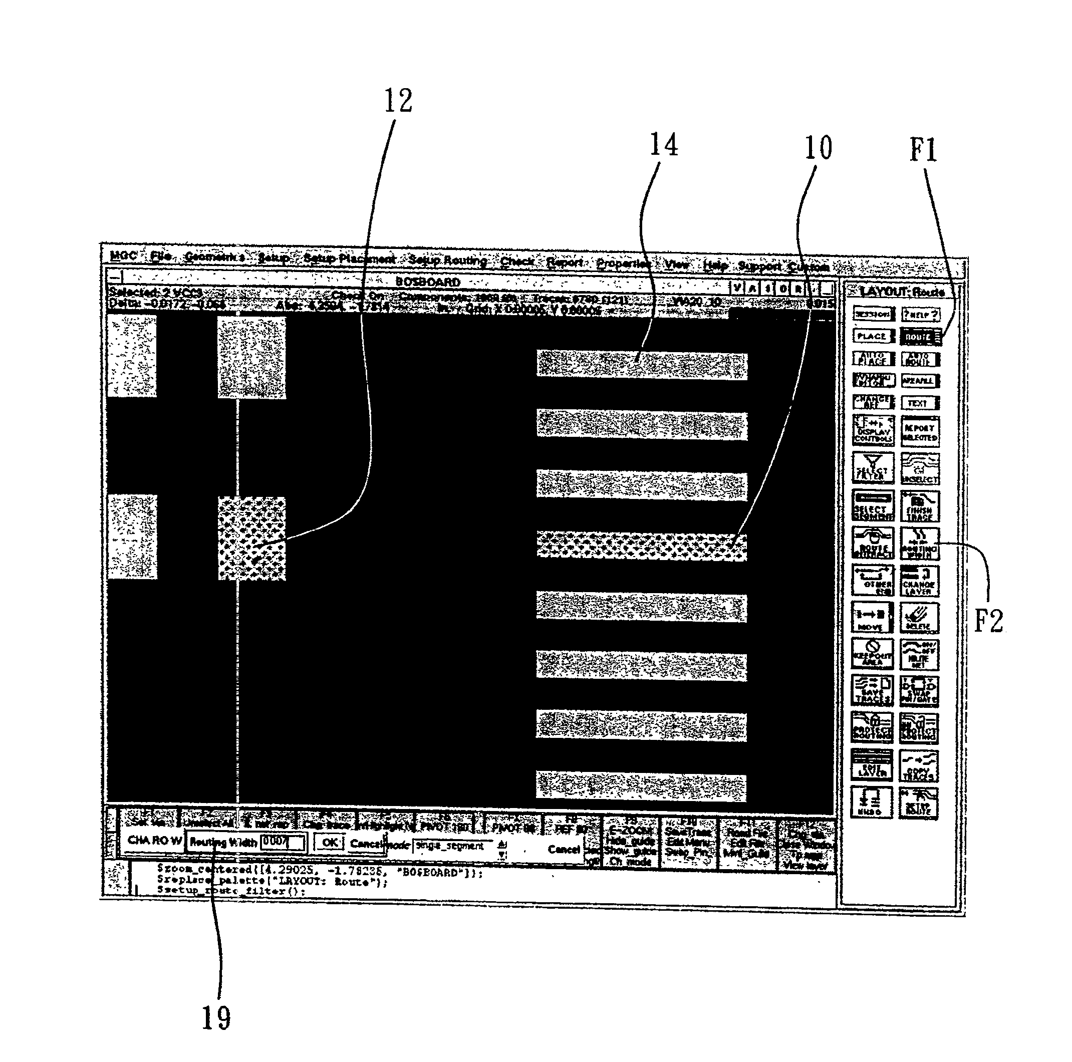
[0036] Such as figure 2 As shown, it is a schematic block diagram of the basic structure of the signal line width control system 2 of the present invention. The signal line width control system 2 of the present invention is loaded into the wiring software to assist the wiring software to perform layout work between at least one pair of pins on a circuit board to be designed. To simplify the description, in the following embodiments, the fir...


PUM


Abstract

A signal cable width adjustment system and method are provided, which is loaded in a cable laying software to assist the software to lay a signal cable between a first connection foot and a second connection foot in designing a circuit board. Besides, a signal cable width, a first connecting foot width, a distance between nearby connection feet of the cable and the first connection foot as well ascoordinate information of the first connection foot and the second connection foot. The system and method mainly extract the signal cable width, the first connecting foot width, the distance betweennearby connection feet of the cable and the first connection foot as well as coordinate information of the first connection foot and the second connection foot via an extraction module, so that a comparison module can compare the width of the first connection foot and the signal cable. When the width of the signal cable is larger than that of the first connection foot, the width of the signal cable that is preset by the cable laying software can be adjusted to the width of the first connection foot by a cable width adjustment module, thus simplifying the operation procedure for cable laying, enhancing the cable laying efficiency, shortening the cable laying period and improving the cable laying quality.

Description

technical field [0001] The present invention relates to a signal line width control technology, in particular to a signal line width control technology that is loaded into wiring software to assist the wiring software in routing signal lines when designing a circuit board. Background technique [0002] With the development of high-density integrated circuits, there is an increasing need to use Electronic Design Automation (EDA) software for wiring. At present, the more common wiring method is the combination of automatic wiring and manual wiring. Because compared with manual wiring, automatic wiring has the characteristics of fast completion speed and high accuracy, and can respond more quickly to market requirements for product design, while manual wiring can make adjustments to partially inconsistent wiring methods to improve wiring. s efficiency. For example, when laying signal lines from one pin (Pin) to another pin on a circuit board, the wiring software can automatic...

Claims


Application Information

Patent Timeline
Patent Type & Authority Patents(China)
IPC IPC(8): G06F17/50
Inventor 许岩杨淑敏黄聪
Owner INVENTEC CORP
Why Eureka
Try Eureka