Damaging apparatus for diffuse shaft cable damage experiment

An axonal injury, diffuse technology, applied in the field of medical research, can solve the problems of death of experimental animals, ignoring the overall movement of experimental animals, brain stem damage and other problems

Inactive Publication Date: 2010-03-24
SHANGHAI JIAOTONG UNIV
View PDF3 Cites 0 Cited by
  • Summary
  • Abstract
  • Description
  • Claims
  • Application Information

AI Technical Summary

Problems solved by technology

[0003] After searching the existing literature, it was found that reference [1] "Establishment of Acute Diffuse Axonal Injury Injury Model and Preliminary Discussion on Injury Mechanism", Chongqing Medicine, Volume 36, Issue 15, August 2007: 1496-1498, and reference [2] "Diffuse axonal injury due to lateral headrotation in a rat model" [J]. J Neurosurg, 2000, 93 (4): 626-633, the DAI injury model developed in only Purely rotating devices and references [3] "A new model of diffusebrain injury in rats, Part I: Pathophysiology and biomechanics" [J]. JNeurosurg, 1994, 80(2): 291-300, only purely striking devices, In the actual injury process, DAI injury is a compound injury mechanism process of impact and rotation, so the existing experimental models have not been able to simulate the actual clinical injury mechanism process of DAI well.
Moreover, the models developed by the above references [1] and [2] did not consider the overall movement of the experimental animal, but only drove the head of the experimental animal to rotate. During the experiment, the twisting of the neck of the experimental animal may seriously damage the brainstem, resulting in Rapid death of experimental animals

Method used


Image

  • Damaging apparatus for diffuse shaft cable damage experiment
  • Damaging apparatus for diffuse shaft cable damage experiment
  • Damaging apparatus for diffuse shaft cable damage experiment

Examples


Embodiment Construction

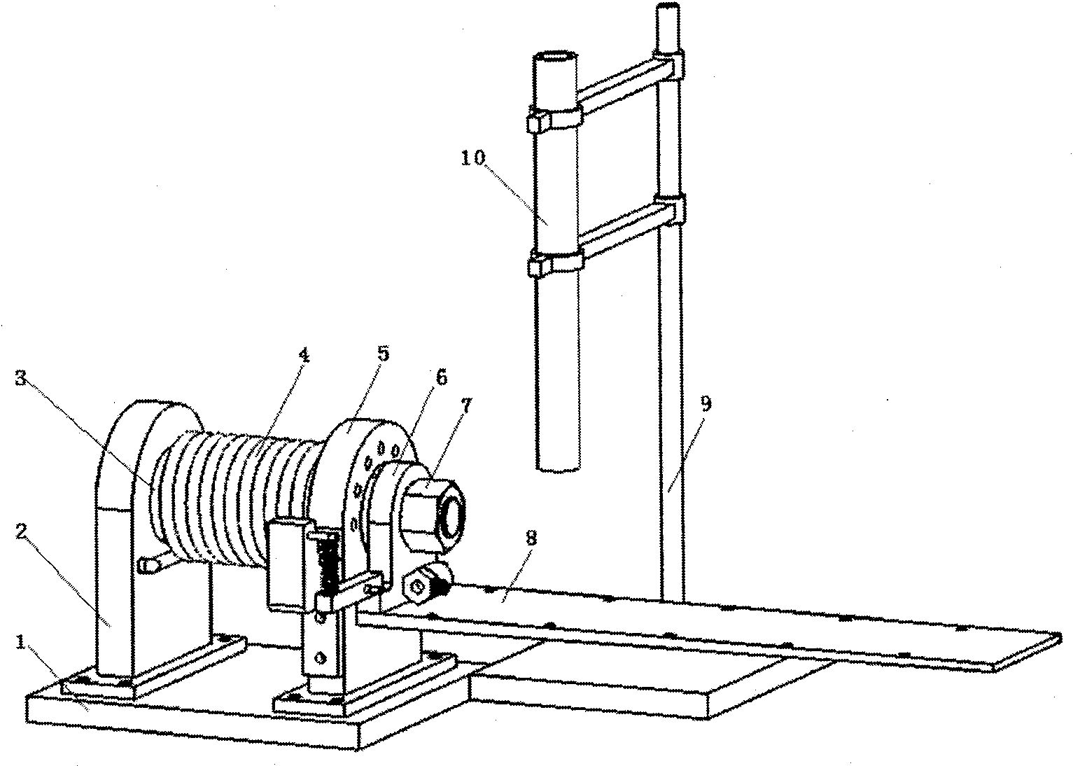
[0022] The embodiments of the present invention are described in detail below in conjunction with the accompanying drawings: this embodiment is implemented on the premise of the technical solution of the present invention, and detailed implementation methods and specific operating procedures are provided, but the protection scope of the present invention is not limited to the following the described embodiment.

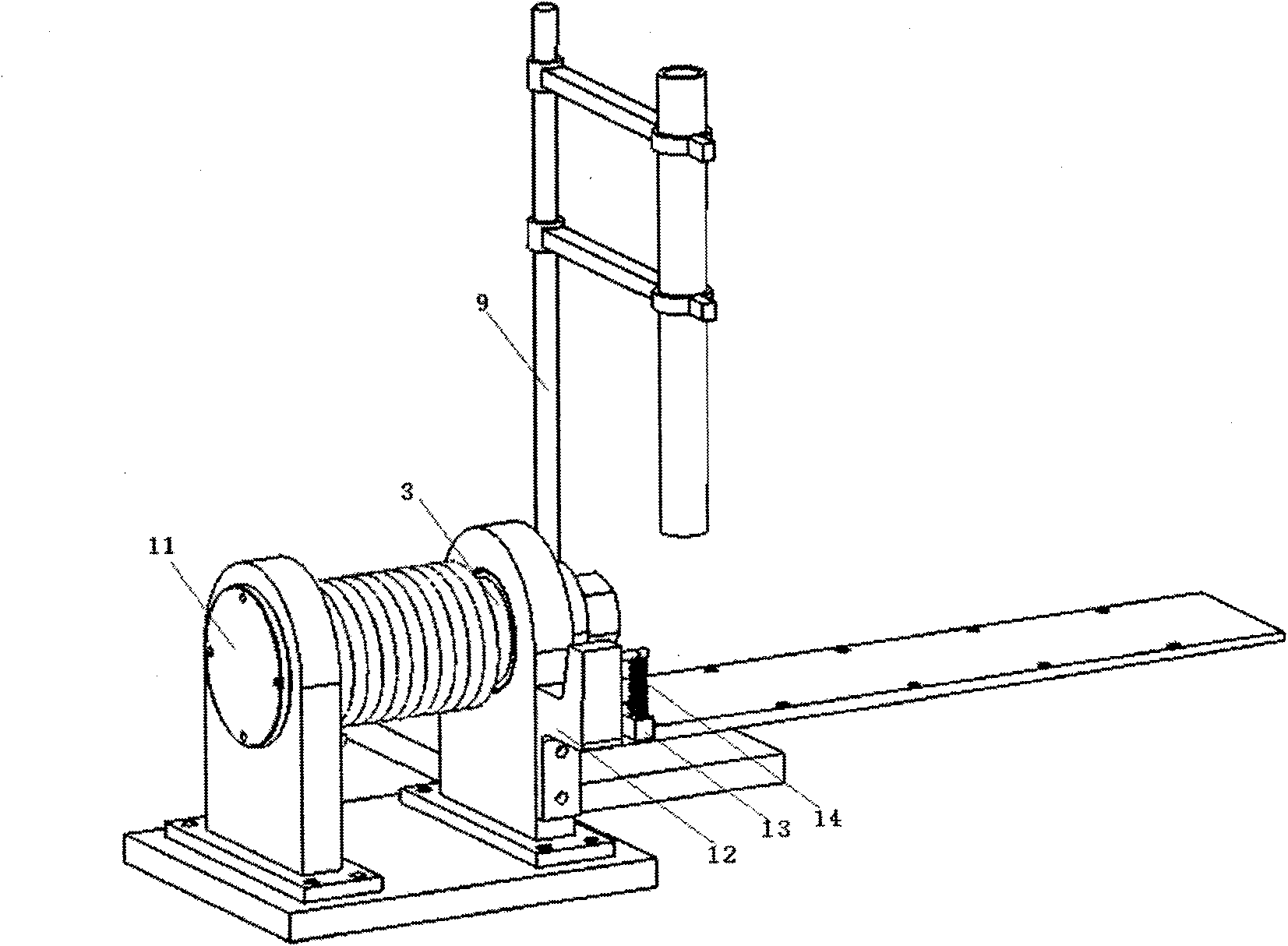
[0023] Such as figure 1 , 2 As shown, this embodiment includes a base 1, two uprights (the first upright 2 and the second upright 5), a shaft 3, a drive actuator 4, a T-shaped coupling 6, an experimental animal placement plate 8, an experimental frame 9, glass Tube 10, end cap 11, pretensioner, sensor 16. The driving actuator 4 is a driving torsion spring, the fixing device 7 is a nut, and the pre-tightening driving device 14 is a tension spring.

[0024] In this example, the two uprights (the first upright 2 and the second upright 5) are fixed to the base 1 with s...


PUM


Abstract

Disclosed is an injury device used in diffusive axonal injury experiment in medical research field. The injury device comprises a pedestal, a first upright post, a second upright post, a shaft, a drive actuator element, a T-shaped connecting piece, an experimental animal holder plate, an experimental stand, a glass tube, an end cap, a pre-tightening device and a sensor. The first upright post andthe second upright pose are fixed with the pedestal. The shaft is installed in the holes at the upper ends of the first upright post and the second upright post. The drive actuator element is arrangedoutside the shaft and is threaded on the shaft. One end of the drive actuator element is fixed on the first upright post and the other end is fixed on the shaft. The circumference of the T-shaped connecting piece is fixed with the shaft. The experimental animal holder plate is fixedly connected with the T-shaped connecting piece. The glass tube is fixed on the experimental stand, and the sensor is fixed on the experimental stand and the T-shaped connecting plate. The pre-tightening device is fixed at the side face of the second upright post. The injury device realizes the functions of impacting and rotation and is more in accordance with the composite impacting and rotation injury mechanism of diffusive axonal injuries.

Description

technical field [0001] The invention relates to a device in the technical field of medical research, in particular to a device for injuring a diffuse axonal injury experiment. Background technique [0002] Diffuse axonal injury (Diffuse Axonal Injury, DAI) is a common craniocerebral injury, characterized by high incidence, severe symptoms, and poor prognosis. It is the main cause of death and disability in patients with craniocerebral trauma. How to prevent and treat diffuse axonal injury in patients with craniocerebral trauma is one of the difficulties in neuroscience research today. The study of DAI injury requires an experimental device with high stability, strong repeatability and a relatively realistic simulation of the clinical injury mechanism of DAI. [0003] After searching the existing literature, it was found that reference [1] "Establishment of Acute Diffuse Axonal Injury Injury Model and Preliminary Discussion on Injury Mechanism", Chongqing Medicine, Volume 36...

Claims


Application Information

Patent Timeline
Patent Type & Authority Patents(China)
IPC IPC(8): A61B19/00G09B23/28A61D1/00
Inventor 谢叻赵志球马延斌王洪财赖芸庄小龙
Owner SHANGHAI JIAOTONG UNIV
Why Eureka
Try Eureka