
Delay self-closing water-saving valve

A water-saving valve and bonnet technology, which is applied in the direction of valve devices, functional valve types, fluid distribution valves, etc., can solve problems such as easy blockage of orifice holes, valve failure, and failure to reset the push rod, so as to achieve stable water discharge and convenient maintenance , the effect of simple structure

Inactive Publication Date: 2007-07-18
CHANGZHOU TEXTILE GARMENT INST
View PDF1 Cites 4 Cited by
  • Summary
  • Abstract
  • Description
  • Claims
  • Application Information

AI Technical Summary

Problems solved by technology

The utility model uses the water flow to control the closing and opening time of the valve, that is, the water flow through the orifice with a small flow area makes the delay control the water internal leakage of the water chamber slower and controls the closing and opening time of the valve. Particles and possible sediment, the orifice of the above-mentioned utility model patent is easy to block, once blocked, the push rod cannot be reset, and the valve will fail

Method used


Image

  • Delay self-closing water-saving valve
  • Delay self-closing water-saving valve
  • Delay self-closing water-saving valve

Examples


Embodiment 1

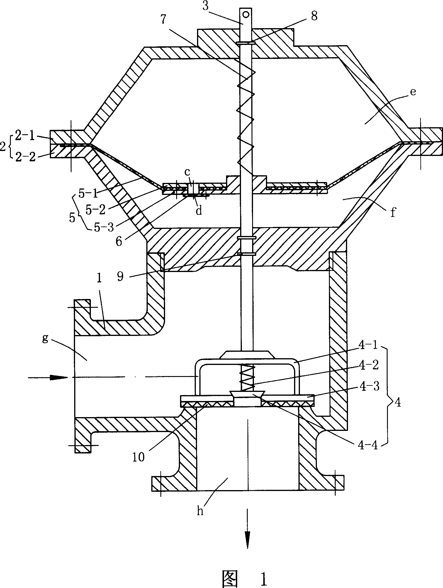
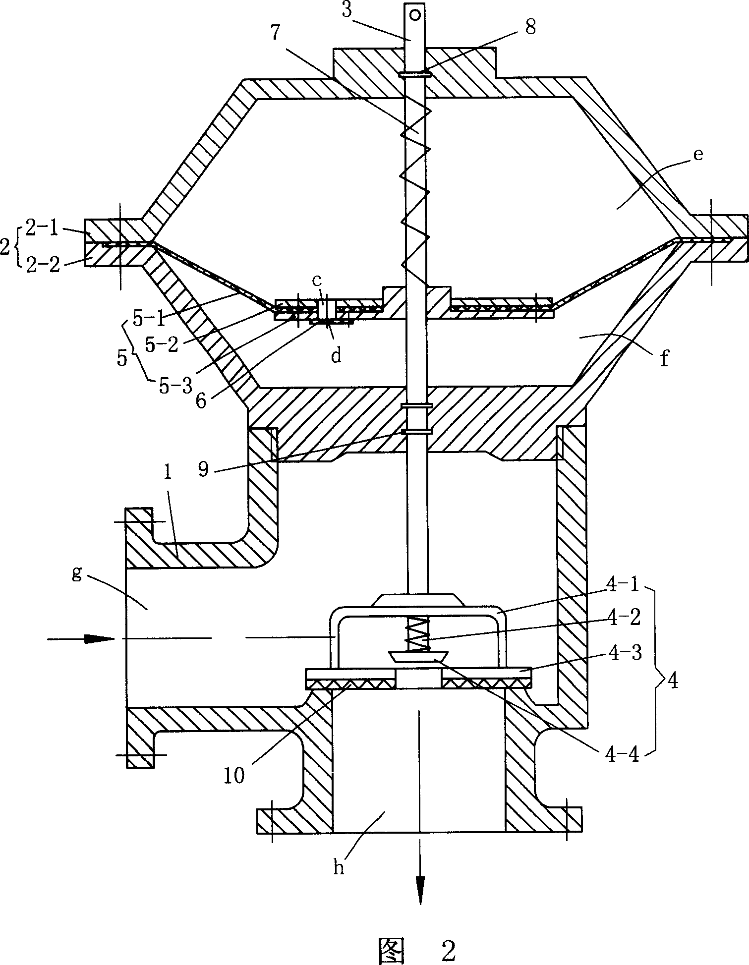
[0024] Embodiment 1 shown in FIG. 1 is in a closed state. This embodiment has a valve body 1 , a valve cover 2 , a valve stem 3 and a valve core 4 , and the valve body 1 is provided with a water inlet g and a water outlet h. The water inlet g is arranged on the side of the valve body 1 , and the water outlet h is arranged at the bottom of the valve body 1 .

[0025] The bonnet 2 is composed of an upper bonnet 2-1 and a lower bonnet 2-2, the lower bonnet 2-2 is threadedly connected with the valve body 1, and the upper bonnet 2-1 and the lower bonnet 2-2 are enclosed by The sealed space is the air cavity, which is provided with an elastic diaphragm 5 that is fixedly clamped between the upper and lower valve covers 2-1 and 2-2. The elastic diaphragm 5 connects the upper and lower valve covers 2-1, The space between 2-2 is divided into an upper air chamber e and a lower air chamber f. The upper valve cover 2-1, the diaphragm 5 and the lower valve cover 2-2 are respectively provi...

Embodiment 2

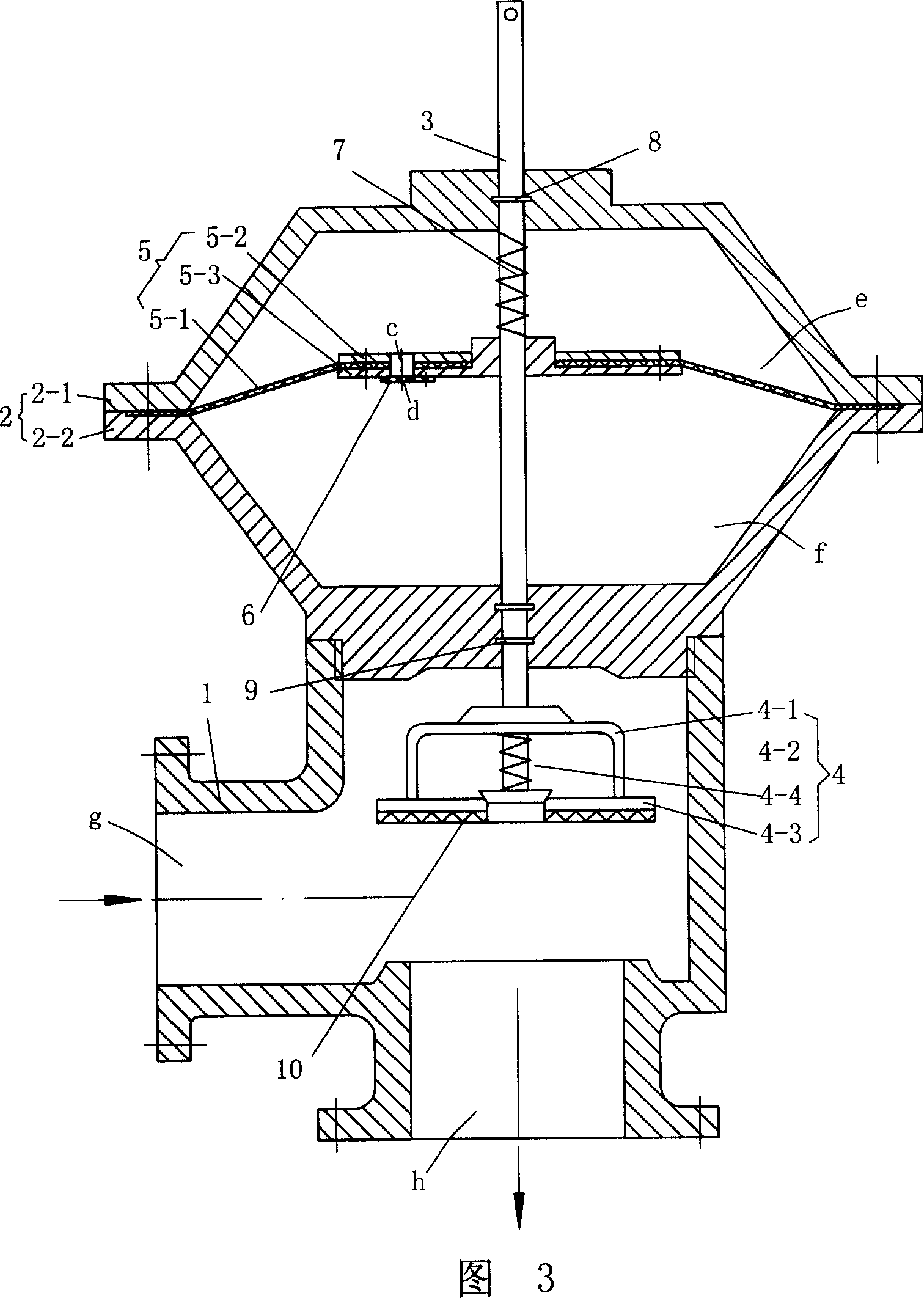
[0031]In this embodiment, the diaphragm 5 includes a disc-shaped diaphragm 5-1, a pressing plate 5-2 fixed on the upper surface of the central part of the disc-shaped diaphragm 5-1, and a pad fixed on the bottom surface of the central part of the disc-shaped diaphragm 5-1 Plate 5-3, the center of the pressure plate 5-2 is provided with a boss 5-21, the pressure plate 5-2 is provided with a valve stem hole passing through the boss 5-21, the disc diaphragm 5-1 and the backing plate 5-3 The parts corresponding to the pressure plate bosses 5-21 are provided with connecting holes. The pressure plate bosses 5-21 pass downward through the connecting holes on the diaphragm 5-1 and the backing plate 5-3, and the valve stem 3 passes through the pressure plate bosses. The valve stem hole of 5-21 is tightly matched with the valve stem hole. The air hole on the pressure plate 5-2 on the same axis, the air hole on the disc diaphragm 5-1 and the air hole on the backing plate 5-3 form the diap...


PUM


Abstract

The invention is a delay self-closing water-saving valve, having valve body, valve cap, valve rod and valve core, where water inlet and outlet are arranged in the valve body, the valve cap is composed of upper and lower valve cap parts, the space the upper and lower valve form is equipped with elastic diaphragm dividing it into upper and lower air cavities, the valve rod runs through the upper valve cap, diaphragm and lower valve cap into the valve body, and the lower end of the valve rod is connected with the valve core, the position on the valve rod and between the upper valve cap and diaphragm is equipped with first spring, the valve rod is in sealing and sliding mode connected with the upper and lower valve caps, fixed with the diaphragm, and the center of the diaphragm is made with air hole, one way valve is arranged corresponding to the air hole and equipped with orifice connected with the air hole. And it adopts mutually separate air cavity and water cavity, and controls valve delay self-closing by air flowing in the two cavities, thus avoiding the orifice jam problem and assuring its quality.

Description

technical field [0001] The invention relates to a time-delayed self-closing water-saving valve Background technique [0002] The delayed water saving valve is a valve that can realize the automatic semi-closing of the delay for an appropriate time after supplying water, which plays the role of water saving. The utility model patent specification with the Chinese Authorization Announcement No. CN2103709Y discloses an adjustable delay self-closing water-saving valve. The water-saving valve has a valve body, a button, a valve stem, a rubber cap, a piston cylinder, a cylinder cover, a piston, Valve plates, etc., the valve body is provided with a water inlet cavity and a drainage cavity, and between the piston cylinder and the valve body, there is an internal leakage channel that communicates with the drainage cavity of the valve body. The variable volume cavity—the time delay control water chamber is enclosed by the cylinder head, the piston and the piston cylinder wall. Press...

Claims


Application Information

Patent Timeline
IPC IPC(8): F16K21/04
Inventor 倪智勤章飞邱铁平刘宏全
Owner CHANGZHOU TEXTILE GARMENT INST
Learn More